Device for heating and moistening a breathing gas

Inactive Publication Date: 2006-01-19
ANTHONY
View PDF15 Cites 50 Cited by
  • Summary
  • Abstract
  • Description
  • Claims
  • Application Information

AI Technical Summary

Benefits of technology

[0013] As used herein a thin layer of water relates to a layer ranging from 0.1 to 0.001 cm. The water evaporation in thin layer permits to avoid pressure build-up in the space between the rigid evaporating body and the heating device. This water evaporation in thin layer in the space allows water feeding by gravity for example and precise vapor output by regulation of the temperature of the heating element.
[0014] In an embodiment of the present invention, said rigid evaporating body is micro-porous. As used herein rigid evaporating body also refers to monolithic body. Furthermore, said rigid evaporating body has substantial water impermeable and water vapor permeable characteristics. Suitable rigid evaporating body can be made of any rigid material known in the art with water impermeable and water vapor permeable characteristics. Said rigid evaporating body is preferably made of solid material having meshes with water impermeable and water vapor permeable characteristics. In an embodiment, the rigid evaporating body can be made of material having a mesh size ranging from 0.05 μm to 1 μm, preferably having a mesh size of 0.2 μm. The use of a rigid evaporating body in the present device provides several advantages such as accuracy and stability of the device. The rigid body does not deform due to heat and pressure caused by the wat

Problems solved by technology

This is necessary, because the nose and throat mucous membranes, which normally take over this task, are no longer available under these circumstances.
Generally the reservoir sized to accommodate enough water to avoid frequent refilling, the entire volume of water in the reservoir is heated to and maintained at the desired temperature so that establishing maintaining and changing the desired water temperature are more difficult than for lesser volum

Method used


Image

  • Device for heating and moistening a breathing gas
  • Device for heating and moistening a breathing gas
  • Device for heating and moistening a breathing gas

Examples


Embodiment Construction

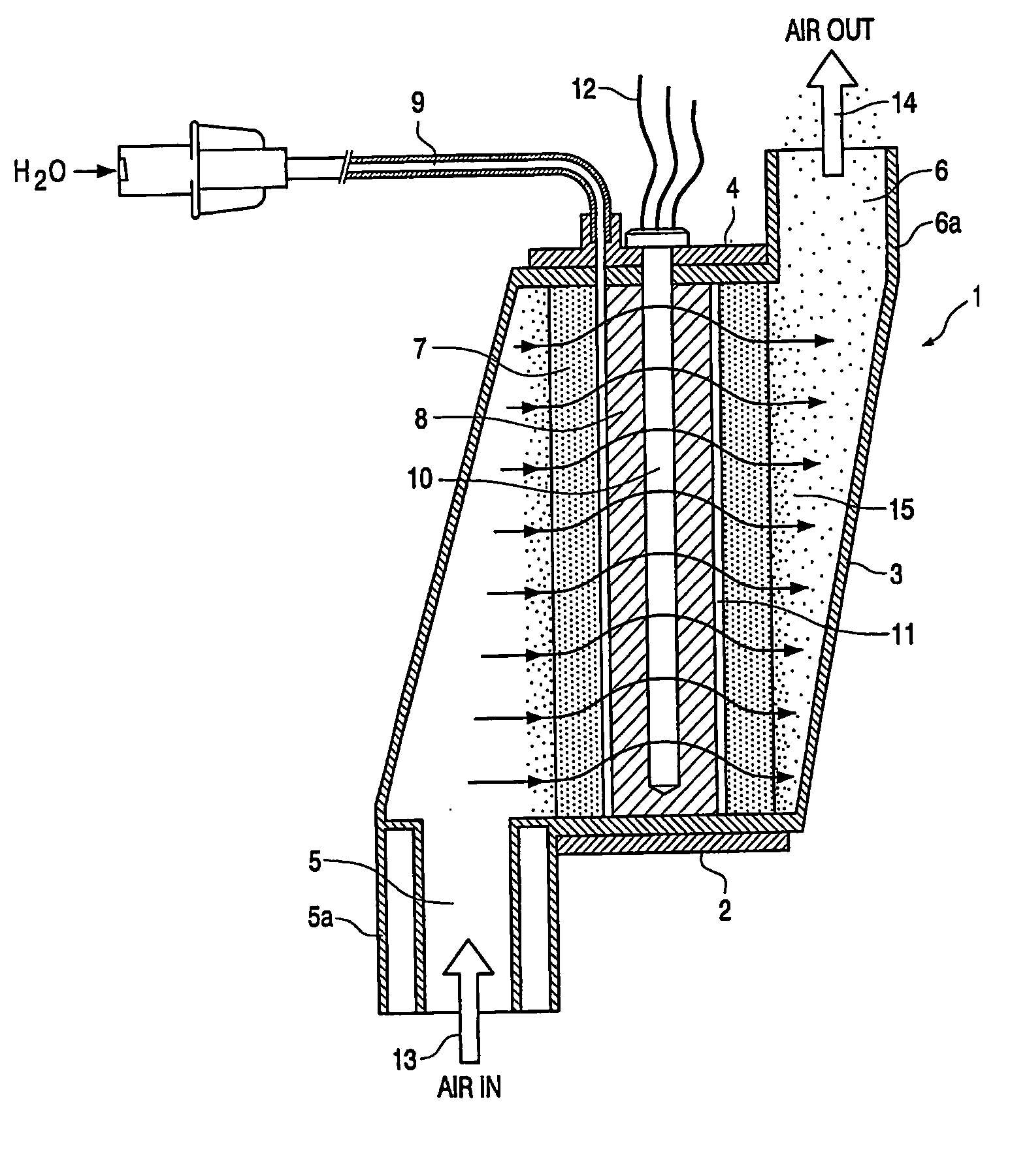
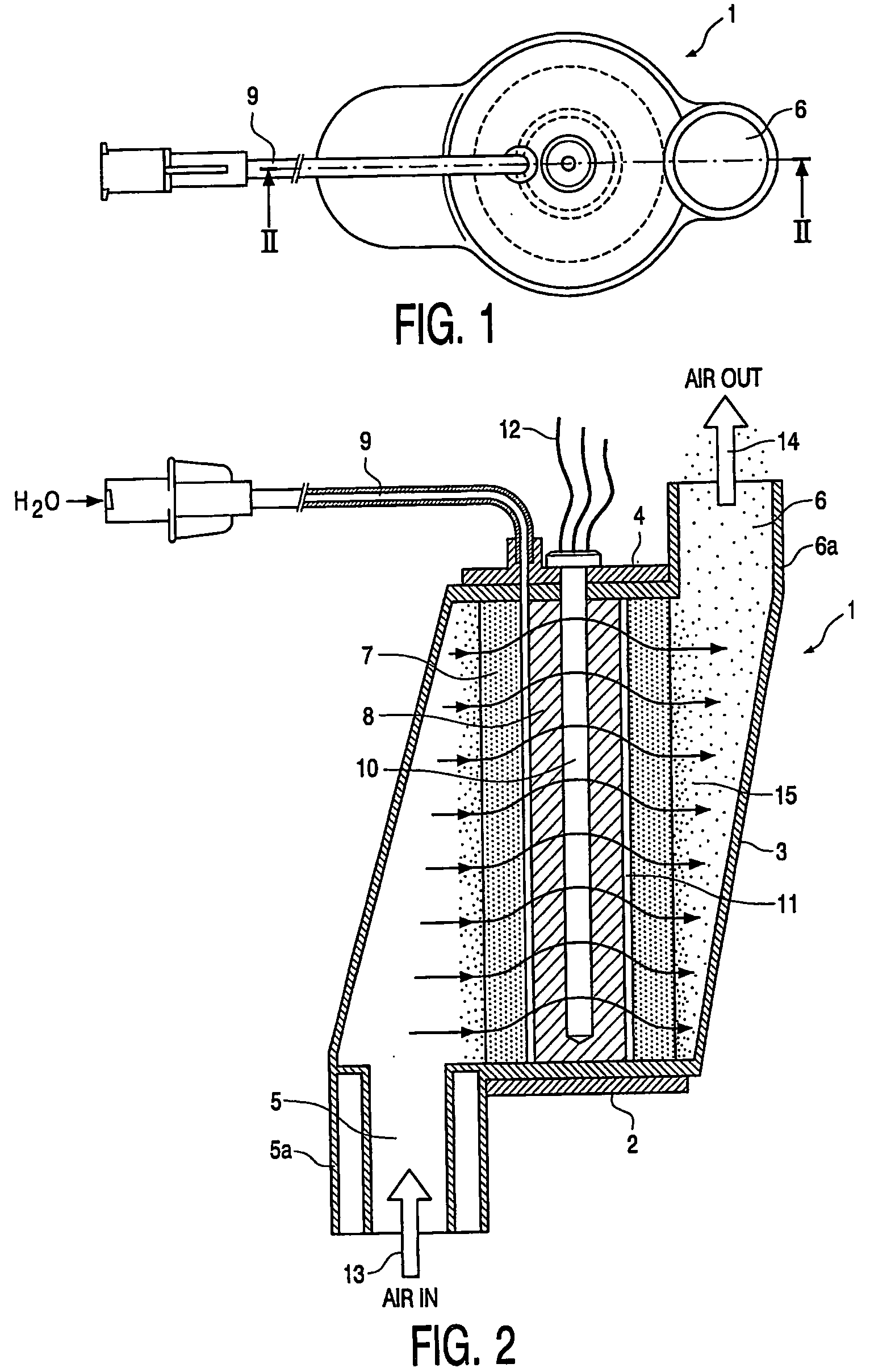
[0027] The present invention relates to a device suitable for the conditioning of medical gas.

[0028] As used herein the term “medical gas” relates to any breathable gas suitable for an individual in need thereof. It also relates to any gas to be delivered to body cavities or organs of an individual in need thereof, such as for example such as normal air to be delivered via nose or mouth to the lungs, or O2 / CO2 gas mixtures to be provided during laparoscopic surgery. As used herein the term “individual” relates to animals, preferably mammals, and more preferably human.

[0029] Said device is particularly suited for the conditioning of breathing air to be supplied to the lungs, and also for the conditioning of gas to be supplied to a body cavity such as in laparoscopic surgery.

[0030] As used herein the term “conditioning of medical gas” and / or “treatment of medical gas” refers to the humidification / moisturizing and the warming of said gas.

[0031] A device according to the invention i...


PUM

PropertyMeasurementUnit
Sizeaaaaaaaaaa
Sizeaaaaaaaaaa
Sizeaaaaaaaaaa

Abstract

The present invention relates to a device for conditioning medical gas comprising a housing provided with an inlet for non treated medical gas and an outlet for the treated medical gas, wherein in said housing conditioning means are provided for the humidification and warming of said medical gas, comprising a rigid evaporating body, a water supply inlet and a heating device, characterized in that said rigid evaporating body and said heating device are arranged in a concentric way forming a space between them and wherein said water supply inlet is connected to the housing such that a thin layer of water is able to be inserted in said space between the heating device and the rigid evaporating body. The invention further relates to a method for the conditioning of medical gas, wherein said gas is humidified and warmed, comprising the steps of supplying through an inlet opening non treated medical gas, humidifying and warming said supplied gas through the action of evaporated water forced through a micro-porous rigid body by heating up a small layer of water.

Description

FIELD OF THE INVENTION [0001] The present invention relates to devices for the conditioning of medical gas and more in particular to humidifiers. BACKGROUND [0002] Under physiological conditions, the nose functions to provide active warming and humidifying of breathing air. However, when a patient is undergoing artificial respiration the nose is shunted by a flexible tube, whose distal end is inserted into the trachea. In order to prevent unwanted effects such as cough stimulus or draining of the mucous membranes, the breathing air supplied must be treated. This is necessary, because the nose and throat mucous membranes, which normally take over this task, are no longer available under these circumstances. The moistening and warming treatment of the supplied breathing gases, which is essential for normal function of the lungs, is nowadays performed by devices usually composed of a humidifying and heating apparatus. [0003] Humidifiers are known in the art. Humidifiers are used to war...

Claims


Application Information

Patent Timeline
IPC IPC(8): B01D47/00A61M16/10A61M16/16
CPCA61M16/1075A61M16/109A61M16/162A61M16/16A61M16/142
Inventor ANTHONY
Owner ANTHONY
Why Eureka
Try Eureka