

Parametric injection molding system and method
- Summary
- Abstract
- Description
- Claims
- Application Information
AI Technical Summary
Benefits of technology
Problems solved by technology
Method used
Image


Examples
Embodiment Construction
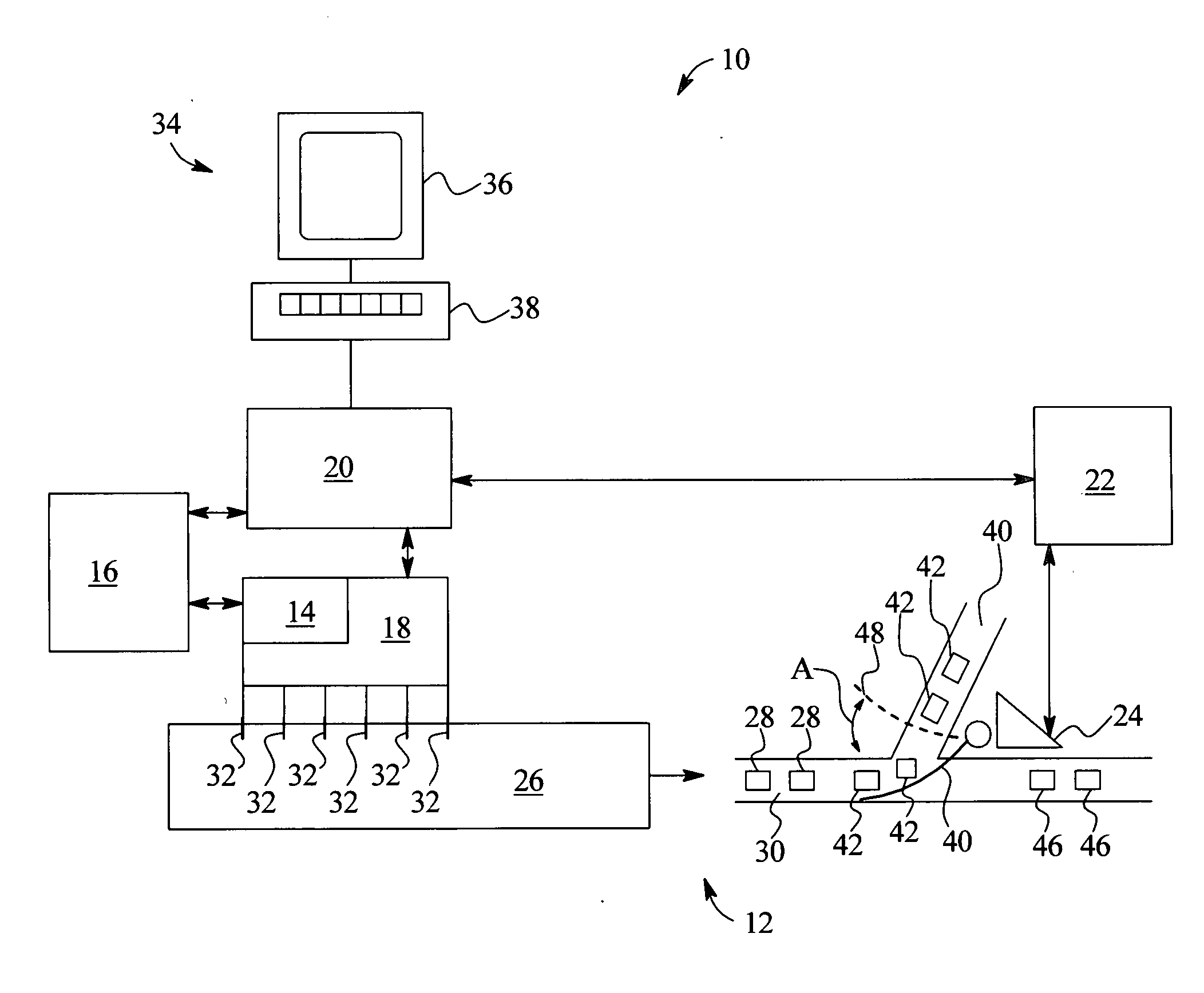
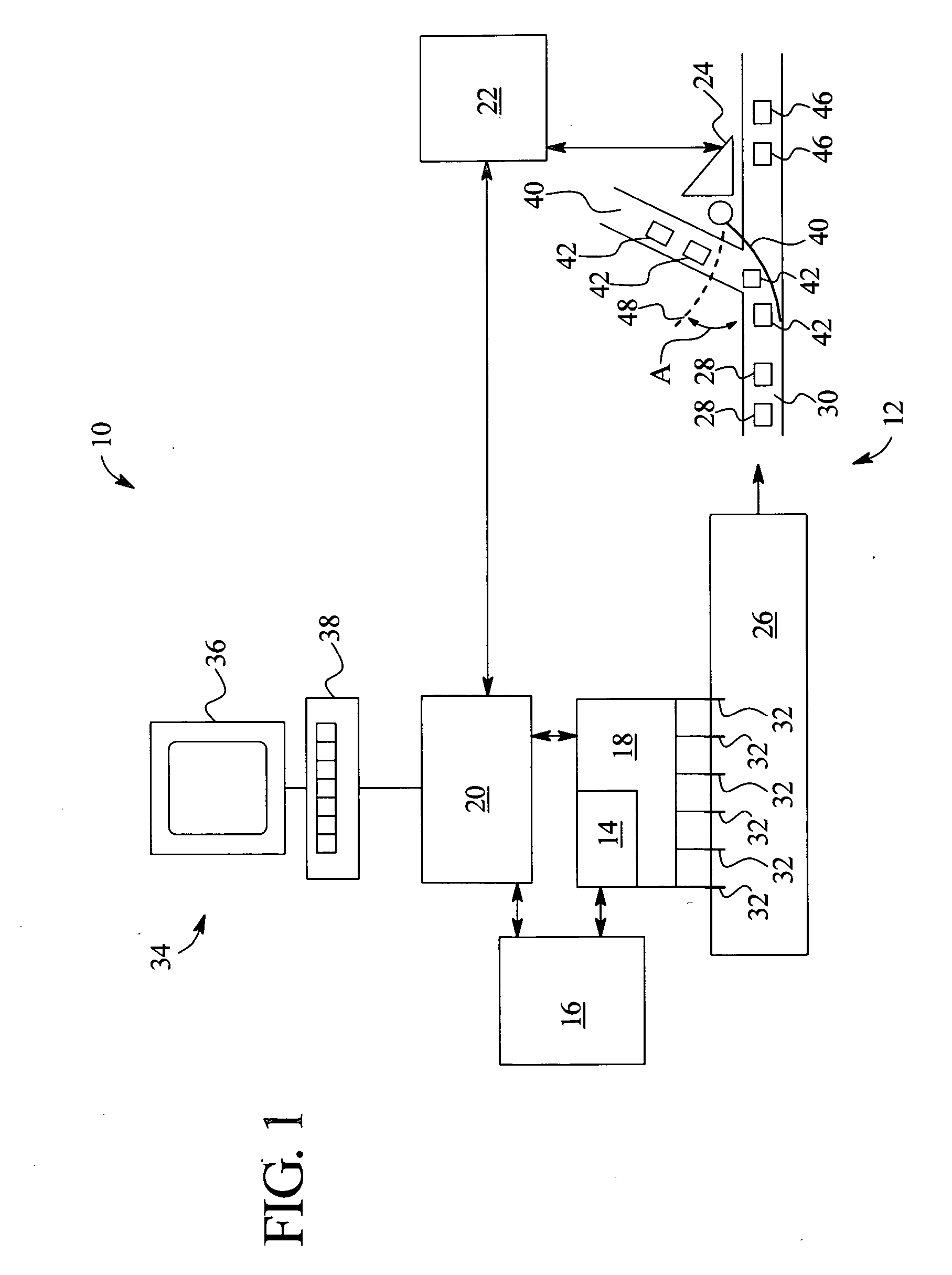
[0011] The present invention generally relates to a parametric release system and method for controlling the quality of a product produced by an injection molding process. A parametric release system is a system that assures that the product produced (i.e., released product) is of the intended quality based on information collected during the production process. Data monitored during the production process is used to maintain real-time process control to assure the quality of the product at a desired level. Product released in a parametric release system is based on data collected during production instead of finished product data or inspection of the finished product. Referring to FIG. 1, where like reference numerals denote like structure and elements, a system 10 for controlling the quality of a product produced by an injection molding process is depicted. System 10 includes an injection molding production process 12, a data storage device 14, a data analysis module 16, a data co...
PUM
 Abstract
Description
Claims
Application Information