Axial field electric machine

a technology of axial field and electric machine, which is applied in the direction of magnetic circuits characterised by magnetic materials, magnetic circuit shapes/forms/construction, magnetic circuit rotating parts, etc., can solve the problems of motor performance not using materials, design steps or construction techniques, and poor efficiency of motor performance, so as to maximize efficiency and motor constant, reduce cost, and maximize efficiency.

Inactive Publication Date: 2006-01-19
SMITH STEPHEN H +1
View PDF0 Cites 42 Cited by
  • Summary
  • Abstract
  • Description
  • Claims
  • Application Information

AI Technical Summary

Benefits of technology

[0017] These and other needs are satisfied by the axial field electric machine of the present invention. Based on the above discussion, the present invention discloses design aspects for an axial field electric machine that maximize efficiency, motor constant, power density, as well as offer the benefits of modular construction, and the potential for reduced cost. Efficiency and motor constant are maximized by maximizing the production of torque while incurring minimal losses. In particular, one aspect of the invention eliminates all ferromagnetic material that incurs core loss, thereby essentially eliminating Pc from Eq. 1, above (although eddy current losses in the conductors must be considered). Doing so increases peak efficiency, broadens the range of speeds over which efficiency is high, and increases power density by eliminating the high mass associated with the added stationary ferromagnetic material. In addition, other aspects of the invention minimizes Pr, which maximize motor constant and maximizes the peak efficiency. Power density is maximized further according to an embodiment of the present invention by optimum selection of the amount of permanent magnet material relative to stator volume. Modular construction allows a whole family of motors at varying power levels to be constructed by stacking sets of identical rotor components and stator components axially within the same motor. Since each rotor and stator is identical, no duplication of capital cost is incurred to produce a whole family of motors. In addition, other aspects of the invention make it possible to select a variety of voltage levels by simply changing the way individual stators are connected, thereby minimizing the inventory required to support a whole family of motors.

Problems solved by technology

As a result, this motor does not utilize materials, design steps, or construction techniques that lead to high efficiency over a broad range of speeds, high motor constant, or high power density.
The floppy disk spindle motor uses an axial field topology solely because there is insufficient axial space available inside the floppy disk housing to use a radial field motor.
In servomotor applications where a motor does not turn continuously but rather starts and stops frequently, efficiency is not a good measure of motor performance because efficiency is zero at zero speed, i.e., ω=0.
In any case, since output power is the product of torque and speed, power density increases linearly with speed to the point where it is no longer possible to maintain torque production, at which point power density decreases.
2, the ability to produce torque is only limited by the ability to remove the heat created by the resulting I2R loss Pr and the speed dependent losses Pc and Pm, which decrease efficiency.
As a result, additional cost is incurred in traditional motors due to the additional capital expense and inventory required to support a family of motors at a given diameter.

Method used


Image

  • Axial field electric machine
  • Axial field electric machine
  • Axial field electric machine

Examples


first embodiment

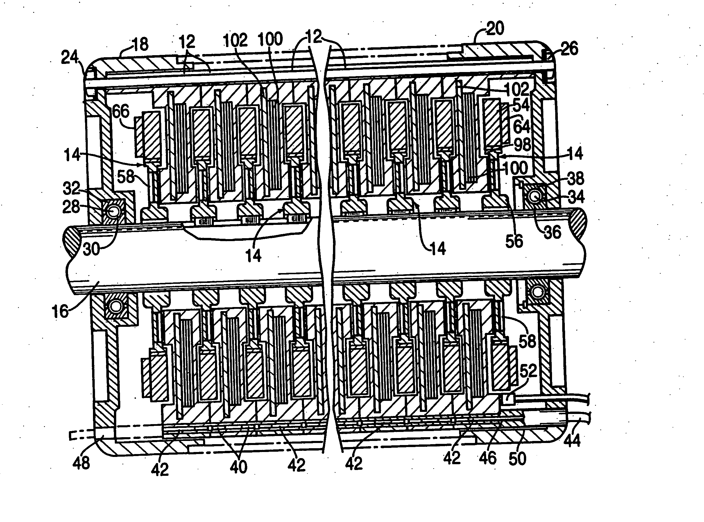
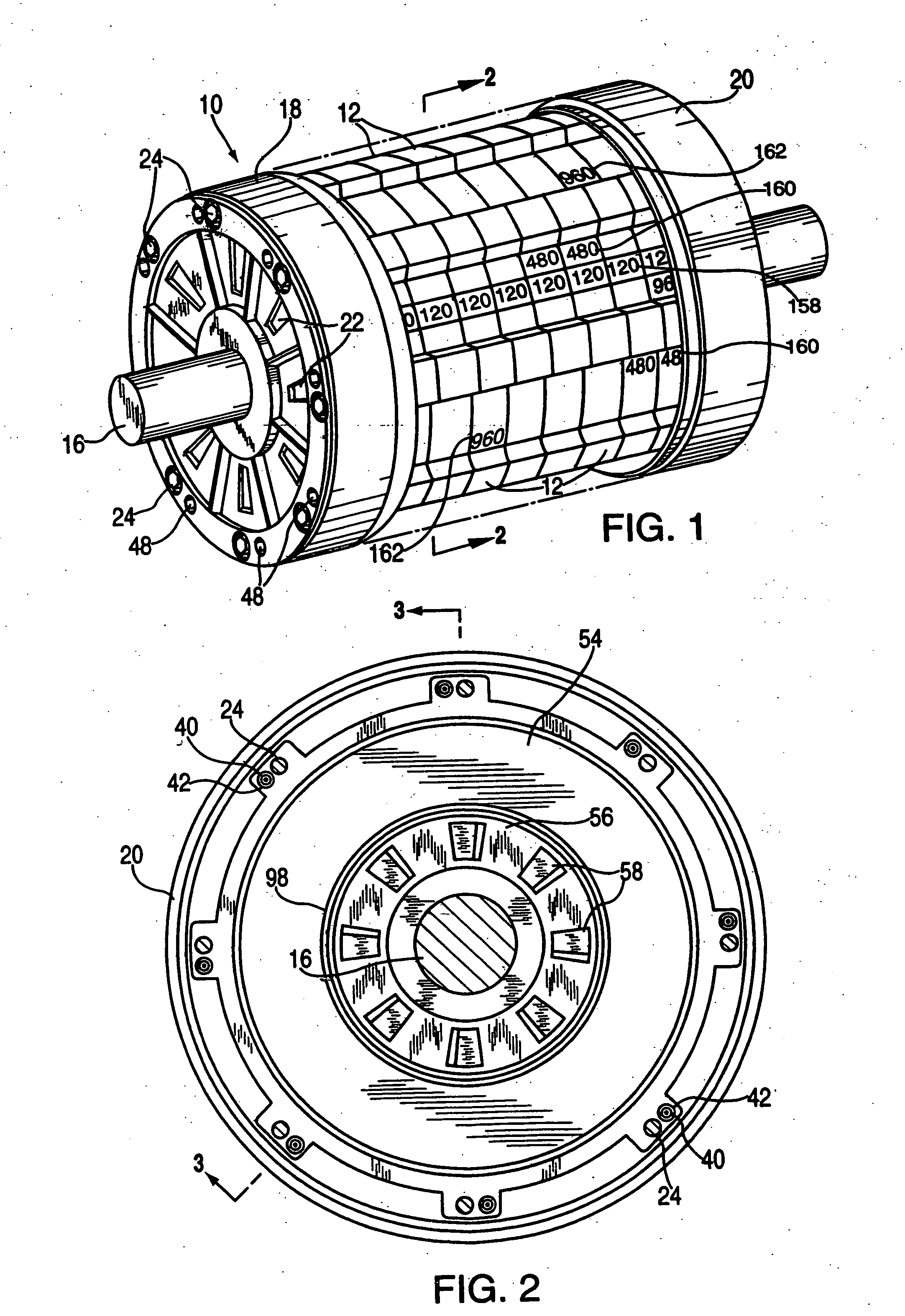
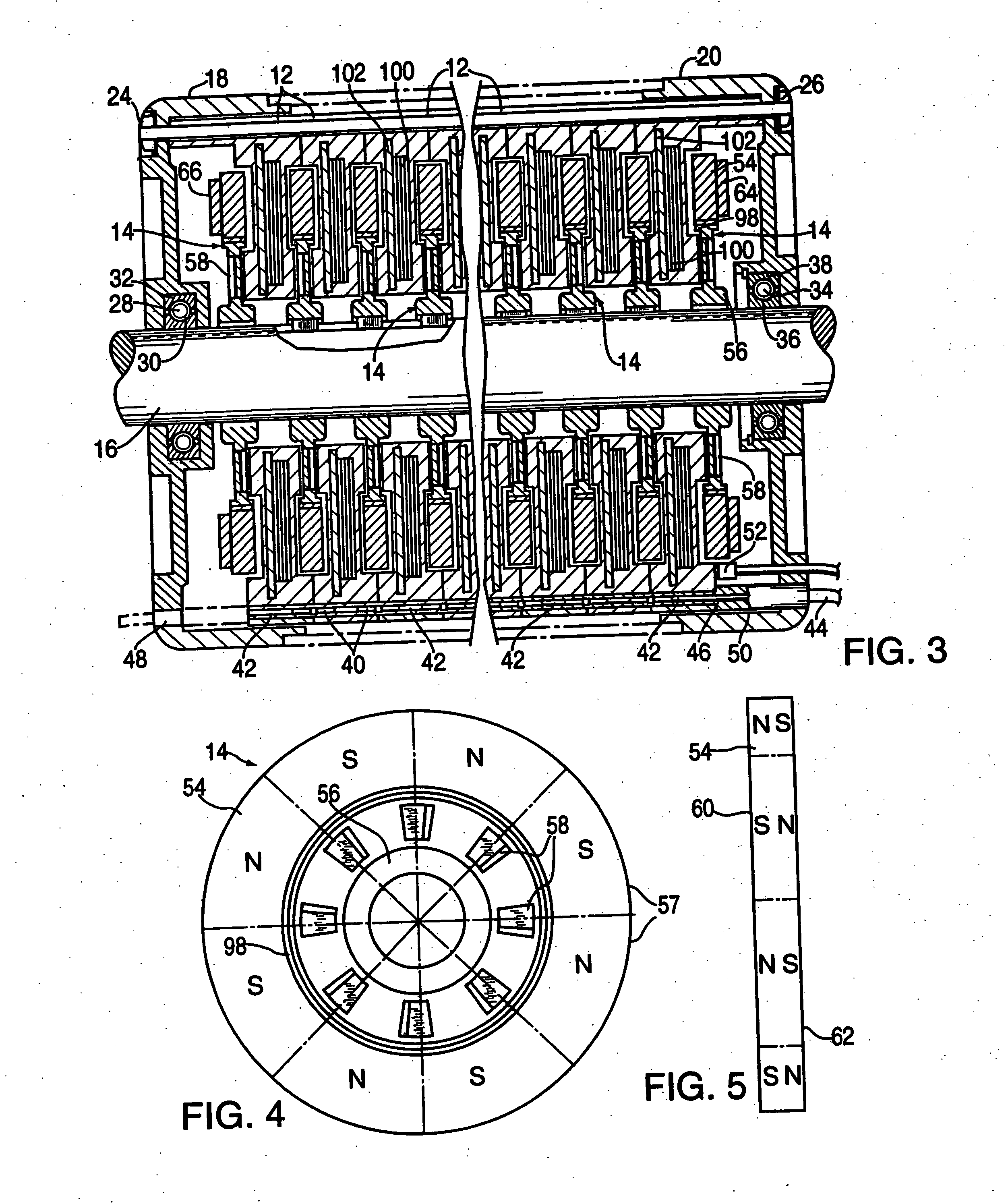
[0077] As illustrated in FIGS. 1-3, a first embodiment of the axial field electric machine designed according to an embodiment of the present invention is shown. The axial field electric machine includes a housing 10 (the center section of which is shown removed), multiple stator assemblies 12 (e.g., each including a conductor element similar to the one shown in FIG. 14) connected to one another and disposed within housing 10, and magnetic elements 14 (e.g., similar to the one shown in FIG. 4) connected to a shaft 16 that extends axially through housing 10. In this example, the conductor elements make up the stator of the electric machine and the magnetic elements make up the rotor. One skilled in the art will appreciate that in an alternative embodiment, conductor elements can serve as the rotor and the magnetic elements can serve as the stator in the electric machine.

[0078] Housing 10 includes two endpieces 18 and 20, each having multiple housing ventilation openings 22. Housing ...

second embodiment

[0089] A second embodiment of the electric machine of the present invention is shown in FIGS. 12, 27-29 using the conductor element of FIGS. 16-20. Referring to FIG. 12, a cross section of this axial field electric machine is shown. The axial field electric machine 200 is similar in construction to the electric machine of FIGS. 1 and 3. Electric machine 200 includes a plurality of magnetic elements 201, such as rotor disks, attached to a shaft 205. In this example, shaft 205 has a configuration similar to that which is shown in FIG. 9. Hubs of axially adjacent magnetic elements are separated by a ring separator 209. Electric machine 200 includes a plurality of conductor elements 202 and connector support elements 203, the construction of which is described in further detail below. As with the electric machine design of FIGS. 1 and 3, electric machine 200 has a modular design in that any number of conductor elements 202 (and connector support elements 203) and magnetic elements 201 m...


PUM


Abstract

An axial field electric machine having an improved efficiency includes a number of magnetic elements (e.g., as a rotor) as annular disks magnetized to provide multiple sector-shaped poles. Each sector has a polarity opposite that of an adjacent sector, and each sector is polarized through the thickness of the disk. The poles of each disk are aligned with opposite poles of each adjacent magnet. Metal members adjacent the outermost disks contain the flux; The axial field electric machine also includes one or more conductor elements (e.g., as a stator) which include a number of conductor phases that traverse the flux emanating between poles of axially adjacent magnetic elements. The design of the axial field electric machine including the gap spacing between adjacent magnetic elements, the transition width between adjacent poles on each magnetic element, the number of poles, the number and width or conductor phases in the conductor element is based on the physical characteristics of the magnetic elements to increase efficiency.

Description

RELATED APPLICATIONS [0001] The present application is a continuation-in-part of U.S. application Ser. No. 08 / 763,824, the disclosure of which is hereby incorporated by reference in its entirety.BACKGROUND OF THE INVENTION [0002] 1. Field of the Invention [0003] The present invention relates generally to electric machines or motor / generators and, more specifically, to permanent magnet, axial field electric machines. [0004] 2. Description of the Related Art [0005] An electric motor / generator, referred to in the art as an electric machine, is a device that converts electrical energy to mechanical energy and / or mechanical energy to electrical energy. Since electric machines appear more commonly as motors the ensuing discussion often assumes that electric energy is being converted to mechanical energy. However, those knowledgeable in the art recognize that the description below applies equally well to both motors and generators. [0006] Electric machines generally operate based on Farada...

Claims


Application Information

Patent Timeline
Patent Type & Authority Applications(United States)
IPC IPC(8): H02K1/22H02K29/00H02K1/02H02K1/18H02K1/27H02K3/04H02K3/26H02K3/28H02K3/34H02K3/46H02K3/47H02K15/03H02K15/16H02K16/00H02K21/24H02K29/08
CPCH02K1/02H02K2203/09H02K1/27H02K1/2793H02K3/04H02K3/26H02K3/28H02K3/47H02K15/03H02K15/165H02K16/00H02K21/24H02K29/08H02K2203/03H02K1/182H02K1/2796
Inventor SMITH, STEPHEN H.SHENKAL, YUVAL
Owner SMITH STEPHEN H
Why Eureka
Try Eureka