
Wristband label assembly with outboard cinch slot

a technology of cinch slot and label assembly, which is applied in the direction of identification means, instruments, and people, etc., can solve the problems of not being able to conveniently associate people desperately in need of health care with their belongings, and not being able to identify body parts. , to achieve the effect of convenient attachment, convenient separation from the carrier, and convenient attachment to a person

Inactive Publication Date: 2006-10-05
ZEBRA TECH CORP
View PDF99 Cites 7 Cited by
  • Summary
  • Abstract
  • Description
  • Claims
  • Application Information

AI Technical Summary

Benefits of technology

The patent text describes a business form that is designed for use in medical emergency situations. The form is a carrier sheet with a wristband / label assembly that can be separated from the carrier sheet. The wristband has a tab and a long strap that can be wrapped around an object, such as a victim's wrist, and then adhered to itself using an adhesive. The form has been developed to address the needs of medical personnel in these situations, who are often wearing gloves and in a hurry. The form is easy to handle, with clumsy fingers, and it can be quickly and easily applied to a victim and their belongings. The form also provides a way to link the identifying information to a triage operation, and it can be adapted to different victim conditions. The form helps to quickly and accurately identify the medical status of a person and their belongings, which can be useful in providing information to families and other loved ones.

Problems solved by technology

In that situation, it became evident that there was no convenient way to associate people desperately in need of health care with their belongings.
Even more horrifying was the need to identify body parts, tag them, their belongings.
Even more horrifying was the need to identify body parts, tag them, and assemble some kind of data base that could be used to sort through the confusion and chaos created on that terrible day.
The environment is usually hostile, with what may be fire, flying debris, collapsing buildings, un-breathable air, etc. which makes it quite different from a usual hospital or other controlled environment and makes handling any “standard” form imminently more difficult.
This sounds easy, but in the chaos of these situations, even with medical personnel who are well trained, there can be lost time in this process and if a good strategy is not used for this classifying, victims can be mis-identified or their status not readily ascertainable after classification, so that the precious time of these “angels of mercy” can be needlessly wasted as they move from one victim to another.
This itself caused much anxiety and pain amongst the survivors.
While not as critical as getting information about survivors to their families, this inability to assemble information created other problems including the inability to gauge the magnitude of the tragedy.
A complete list of the survivors was impossible to assemble for days, even though information was individually available by then.
There just was not a convenient way to assemble this information in a common data base.
Some attempts were made to use the internet, but inaccuracies abounded and the information posted there was soon being ignored, at least part due to the lack of confidence in that information.
In this arrangement, adhesive is applied to join the top and bottom lamination portions, but it does not aid in holding the strap in position unless the nurse takes the time and is able to obtain the cooperation of the patient to thread the strap through only one of the slots before folding the lamination halves together to enclose the face stock.
However, this is thought to be a less desirable attachment arrangement than first enclosing the face stock and then threading the strap through the slot.

Method used


Image

  • Wristband label assembly with outboard cinch slot
  • Wristband label assembly with outboard cinch slot
  • Wristband label assembly with outboard cinch slot

Examples


Embodiment Construction

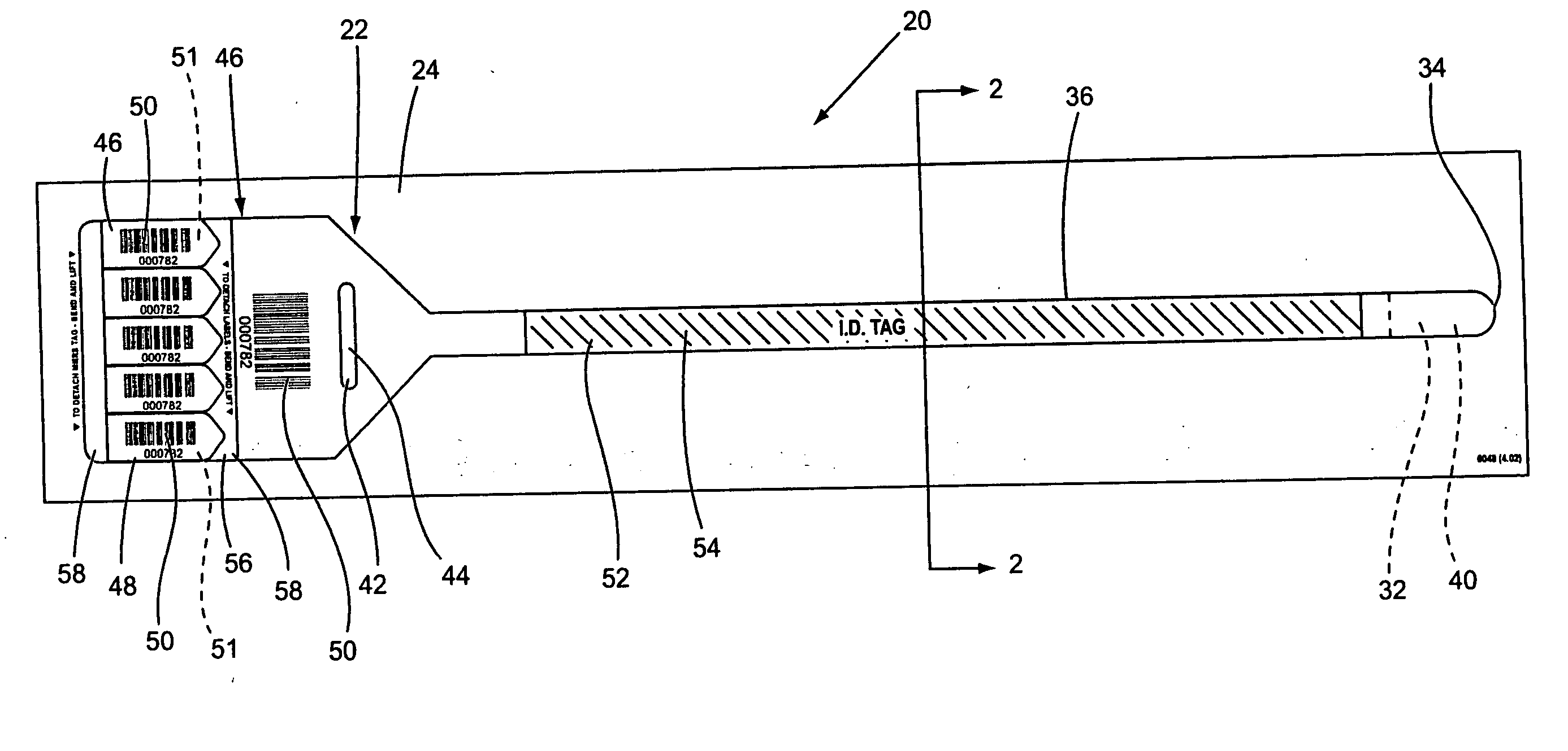
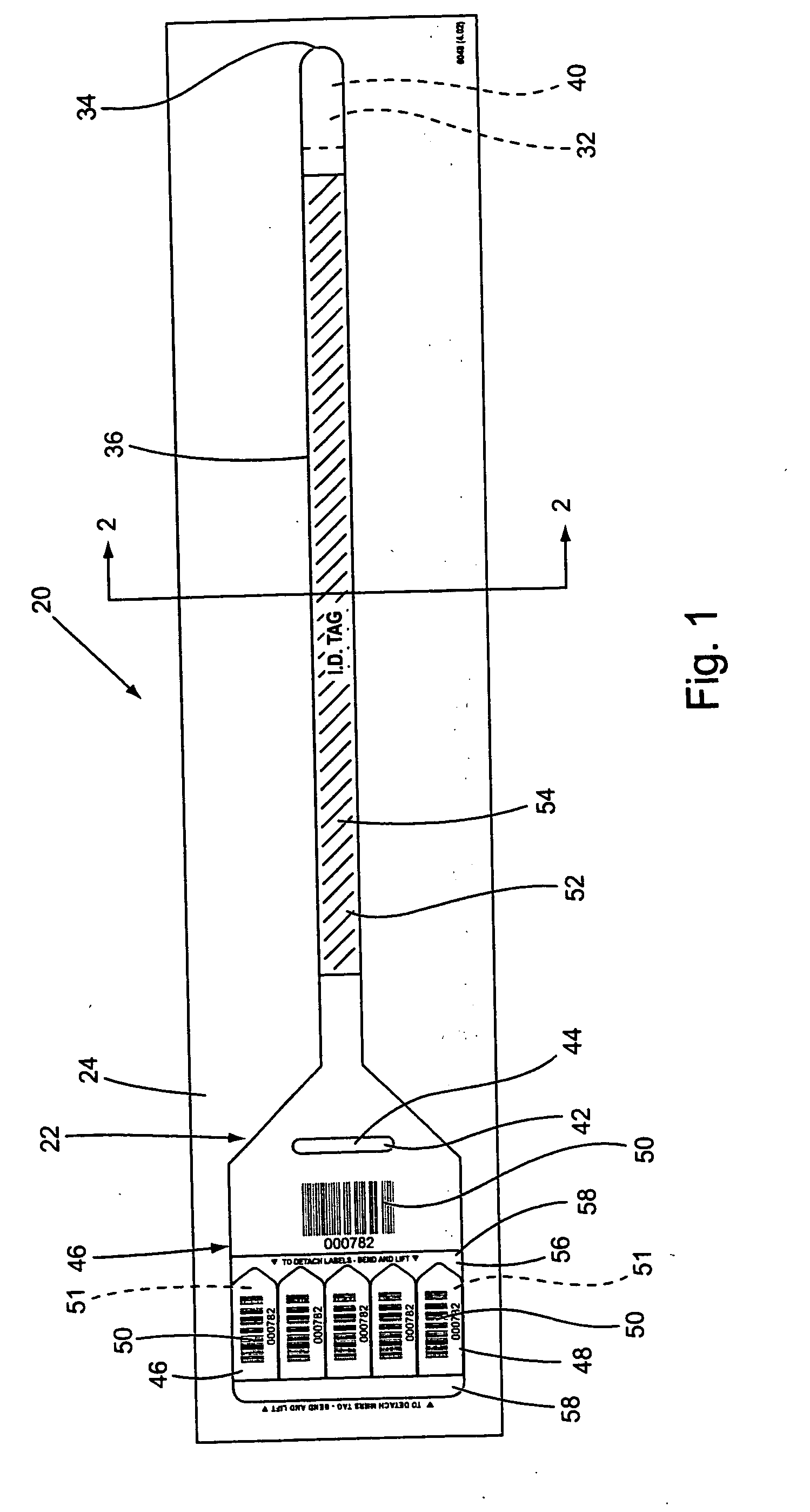
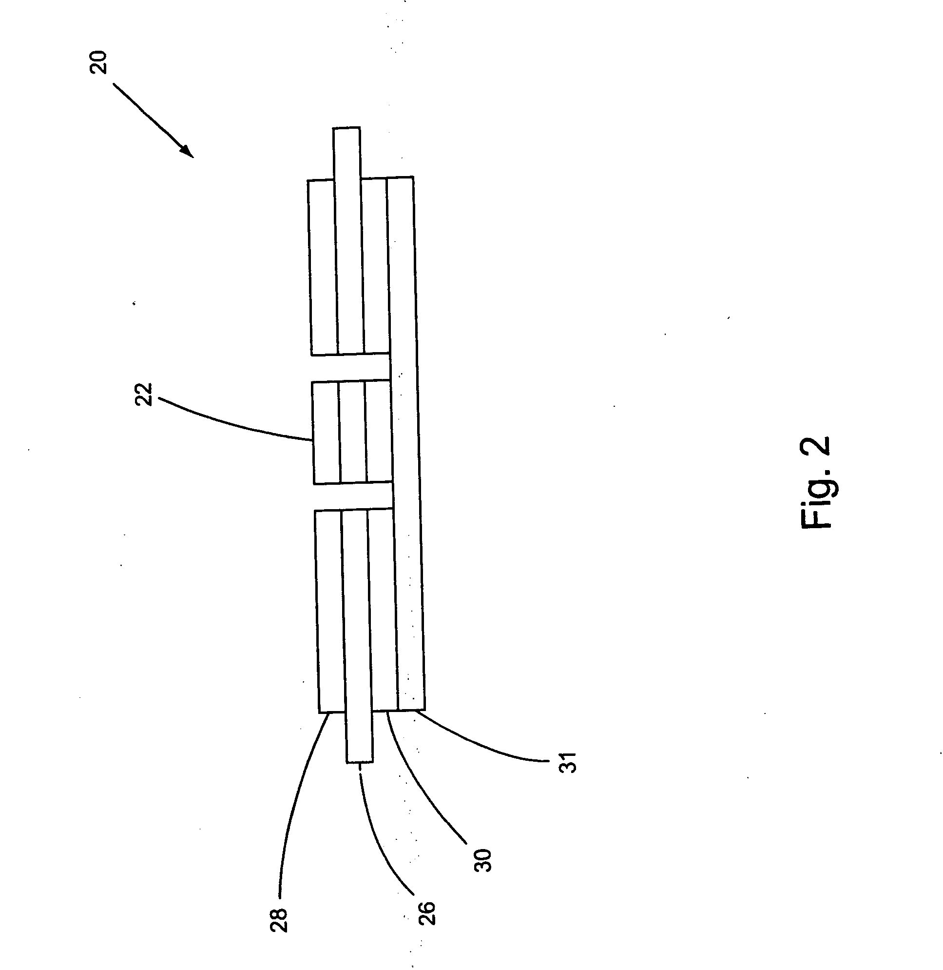
[0041] As shown in FIGS. 1-3, the first embodiment of the business form 20 of the parent invention generally includes a wristband / label assembly 22 die cut into a carrier 24 making an overall size of preferably approximately three and a half inches by seventeen inches, (3½″×17″). Generally, the business form 20 is assembled with a three web construction, with a poly laminated paper center web 26 sandwiched between a pair 28, 30 of thin film poly, transparent webs, and this is then dry adhered to a carrier web 31. The poly coated paper web 26 is dry adhered to the carrier web 31 so that it may be separated therefrom along its die cut to remove the wristband / label assembly 22 from the carrier 24. At an end of the form 20, an adhesive 32 is applied to the single end 34 of the wristband portion 36 of the wristband / label assembly 22. A separate patch 40, preferably made of paper with a release coating, covers the adhesive 32, with the webs die cut so that a portion of the patch 40 coveri...


PUM


Abstract

A business form particularly adapted for generalized use, although it may be used in a medical or hospital environment includes in a first embodiment a wristband that is provided with a laminate backing including a tab portion at the opposite end of a free end, with the tab portion having a cinch slot through which the free end is inserted for securing the wristband about a person's appendage. Several self adhering labels are provided inboard of the tab and may be individually separated from the wristband. The labels and the wristband may each be imprinted with identifying indicia such as bar coding. A second embodiment of the invention includes a page sized form with one or more self laminating wristbands readily separable from a carrier with each wristband comprised of a layer of face stock and a laminate, with the wristband including a printable face stock region die cut into the face stock and a strap portion, a laminating portion, and a cinch die cut into the laminate layer. The laminating portion includes two halves which fold together about a fold line to enclose the face stock, with the strap portion extending from one of said halves. The cinch comprises two slots which may both be located outboard of the face stock, or on both sides of the face stock. The free end of the strap may be adhered in place by folding over one of the slots, or by adhering a patch of adhesive carried at the tip of the free end. The face stock may be extended to the edge of the cinch slot to shield the strap from contacting adhesive. Any of the wristband constructions may be provided on a page sized sheet along with a plurality of self adhering labels, in any of a number of configurations, to suit any particular application, as desired by a user.

Description

CROSS REFERENCE TO RELATED APPLICATION [0001] This application is a continuation of Ser. No. 10 / 627,135 filed Jul. 25, 2003, which has been allowed, which is continuation-in-part to Ser. No. 10 / 283,777 filed Oct. 30, 2002, which has been allowed, which is a continuation-in-part of Ser. No. 10 / 256,758 filed Sep. 27, 2002, which has been allowed, the disclosures of which are incorporated herein by reference.BACKGROUND AND SUMMARY OF THE INVENTION [0002] There are many situations where it would be convenient to have available a way to separately identify a person, such as a health care patient, with his / her possessions or other related items with which the person needs to be associated. As this is written, the recent events of the tragedy of Sep. 11, 2001 have provided a glaring example of one such situation. In that situation, it became evident that there was no convenient way to associate people desperately in need of health care with their belongings. Even more horrifying was the ne...

Claims


Application Information

Patent Timeline
Patent Type & Authority Applications(United States)
IPC IPC(8): A44C5/00G09F3/00
CPCB42D15/00G09F3/005B42P2241/22A61B90/94A61B2090/08021
Inventor RILEY, JAMES M.
Owner ZEBRA TECH CORP
Learn More