
Control system for an electric machine

Active Publication Date: 2006-01-19
CARRIER CORP
View PDF13 Cites 21 Cited by
  • Summary
  • Abstract
  • Description
  • Claims
  • Application Information

AI Technical Summary

Benefits of technology

[0011] According to another aspect of the invention, there is provide a method of controlling a system variable in a control system for an electric generator. The system variable has a set-point value and the electric generator has an output signal. The method comprises sensing the output signal and providing a sample signal representative thereof. Providing a proportional signal proportional to the sample signal. Integrating the sample signal and providing an integral signal. Differentiating the sample signal and providing a differential signal. Providin

Problems solved by technology

There is an error generating means that provides an error signal.

Method used


Image

  • Control system for an electric machine
  • Control system for an electric machine
  • Control system for an electric machine

Examples


Embodiment Construction

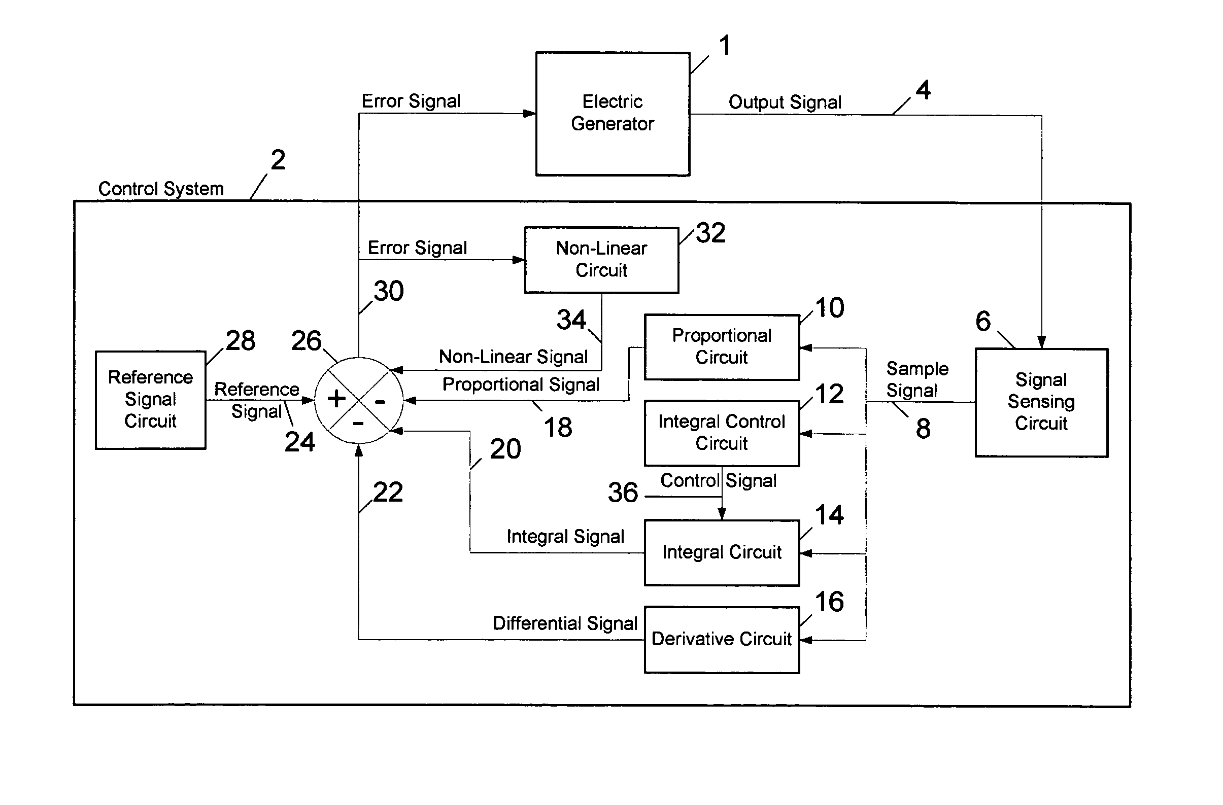
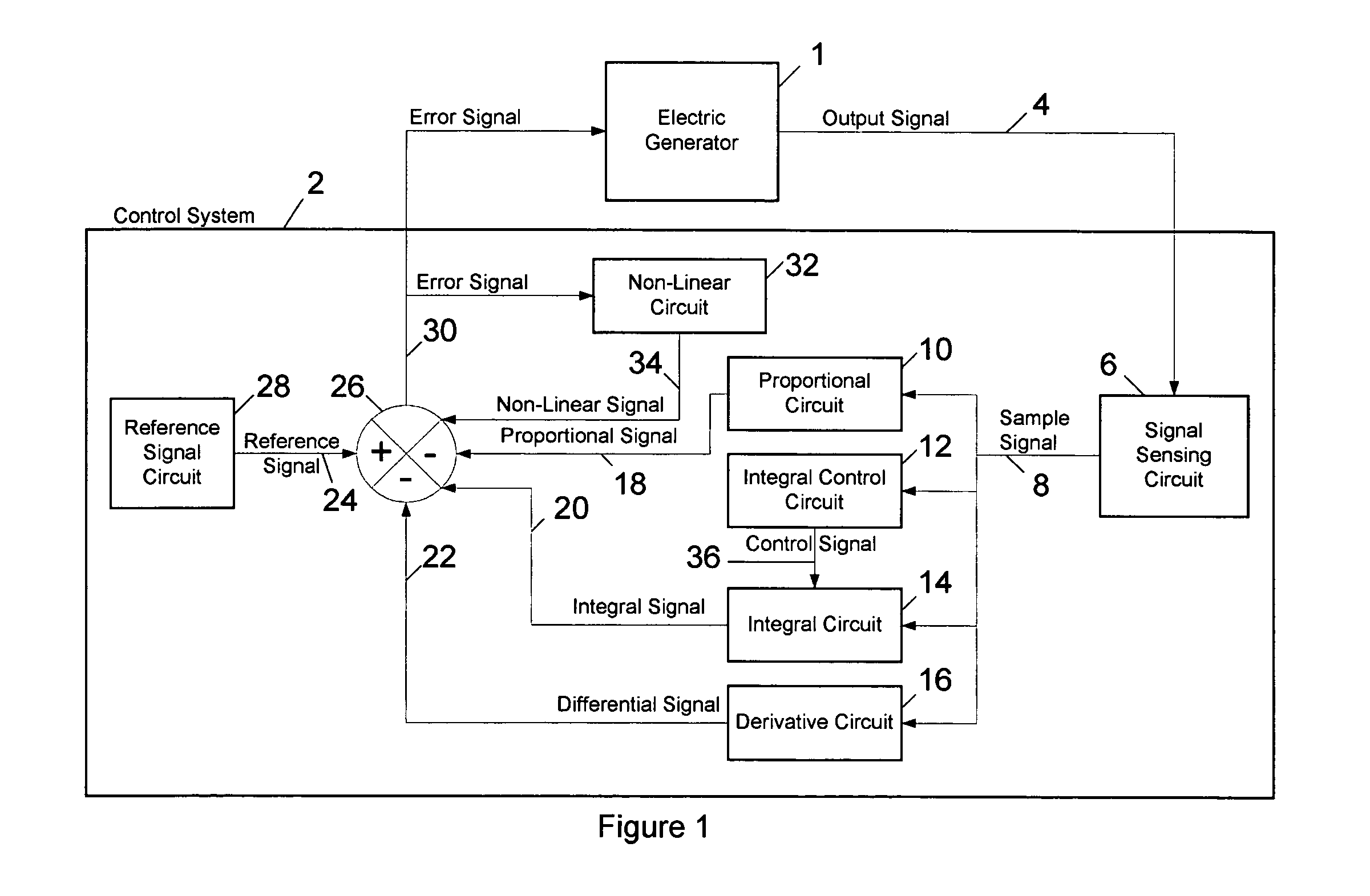
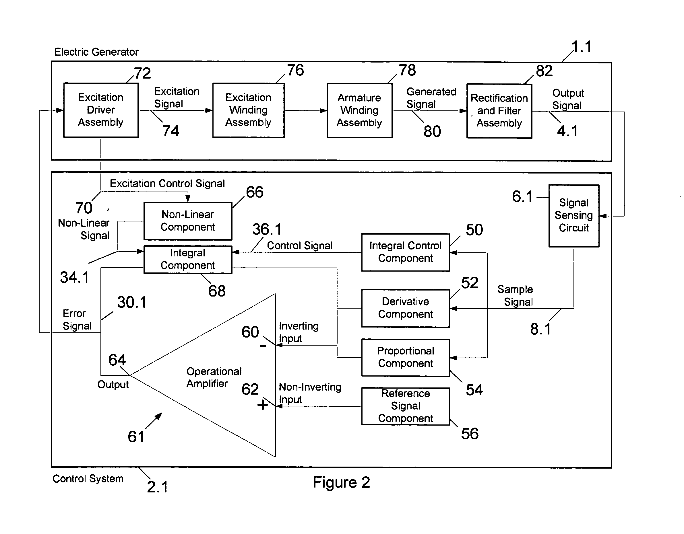
[0033]FIG. 1 shows a preferred embodiment of a control system 2. According to the present invention, an electric generator 1 provides an output signal 4. The output signal 4 in the present embodiment is a DC voltage signal that has a set-point value. The controlling elements within the control system 2 include a proportional means 10, an integral means 14, and a derivative means 16, together forming a PID feedback control element. In other embodiments of the invention, the control system 2 may comprise the integral means 14 and not the proportional means 10 and derivative means 16, or the proportional means 10 and the integral means 14 and not the derivative means 16, or the derivative means 16 and the integral means 14 and not the proportional means 10. An integral control means 12 serves to control integral means 14. Additionally, a non-linear means 32 provides a further element of control by counteracting non-linear effects within the electric generator, as will be discussed belo...


PUM


Abstract

There is provided an adjustable integral component in a feedback loop of a closed loop control system. The closed loop control system controls an output signal of an electric generator. The adjustable integral component provides an integral signal. The integral signal is proportional to the output signal in a first operational mode. The integral signal is proportional to a time integral of an output signal in a second operational mode. According to another aspect of the invention there is provided a non-linear component in a feedback loop of a closed loop control system. The closed loop control system controls an output signal of an electric generator. The electric generator having non-linear characteristics. The feedback loop has an error signal, of which the output signal is responsive to. The non-linear component receives a load signal and provides a non-linear signal related to the non-linear characteristics of the electric generator. The error signal is responsive to the non-linear signal. According to another aspect of the invention, there is provided a method of controlling a system variable in a control system for an electric generator. The output signal of the electric generator is sensed and a sample signal is provided thereof. The sample signal is compared to be below a threshold value, and accordingly an adjustable impedance is adjusted to be substantially resistive. A proportional signal and integral signal that are proportional to the sample signal are provided. A time derivative is taken of the sample signal to provide a differential signal. An error signal is generated by providing a difference between a reference signal and a sum of the proportional signal, the integral signal and the differential signal. The output signal is then adjusted based on the error signal, by driving the output signal towards the set-point value. The sample signal is then compared to be above the threshold value, and accordingly the adjustable impedance is adjusted to be substantially capacitive. The integral signal now being representative of a time integral of the sample signal.

Description

BACKGROUND OF THE INVENTION [0001] 1. Field of the Invention [0002] The present invention relates to a closed loop control system used in electric machines, and in particular electric generators. The control system is used to maintain an output voltage of the electric generator at a set-point value in a steady state condition. Additionally, the control system provides a timely response to changes in output voltage under transient conditions, such as a change in load or generator speed, to restore the output voltage to the set-point value. [0003] 2. Description of the Related Art [0004] Various circuits have been introduced for use in closed loop control systems. As an example, U.S. Pat. No. 5,298,845 issued Mar. 29, 1994 to David P. DeBoer et al. describes a proportional plus integral controller operating an actuator in an HVAC system. This controller enables an integral part of a PI controller only when the error signal exceeds a predetermined value. A disadvantage of this method i...

Claims


Application Information

Patent Timeline
IPC IPC(8): H02H7/06H02P11/00H02P9/00
CPCH02P9/305
Inventor VELHNER, ALEKSALLYN, NEIL GARFIELDMOREAU, TERRY
Owner CARRIER CORP
Learn More