Apparatus and method for driving plasma display panel

a plasma display panel and apparatus technology, applied in the direction of instruments, static indicating devices, etc., can solve the problems of data drive ic failure or abnormal operation, data drive ic failure or more serious problems,

Inactive Publication Date: 2006-01-19
LG ELECTRONICS INC
View PDF9 Cites 6 Cited by
  • Summary
  • Abstract
  • Description
  • Claims
  • Application Information

AI Technical Summary

Benefits of technology

[0057] Another object of the present invention is to provide a scan drive apparatus and method for a plasma display panel, by which the size of th...

Problems solved by technology

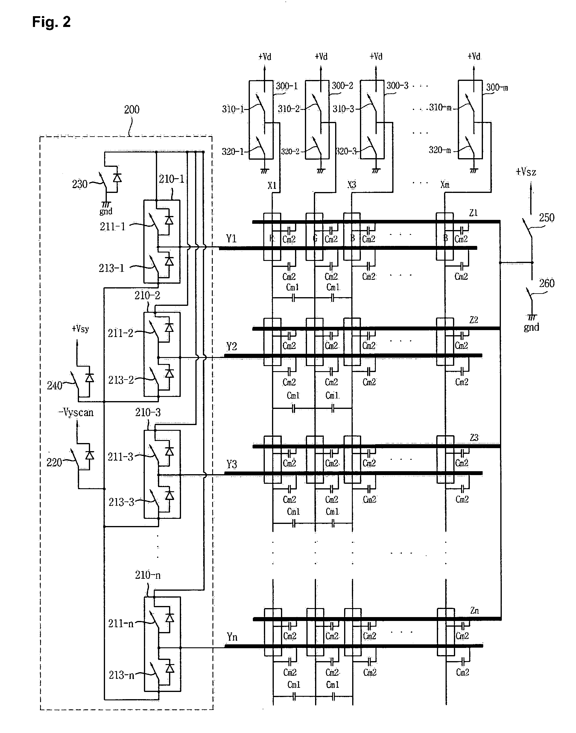
However, the maximum displacement current Id can cause damage to the data driver ICs 300-1 to 300-m.
The grid type image is used in half-toning to improve the image quality of ...

Method used


Image

  • Apparatus and method for driving plasma display panel
  • Apparatus and method for driving plasma display panel
  • Apparatus and method for driving plasma display panel

Examples


first embodiment

[0111] A first decoder Dec1 receives, in parallel, a 1-bit output signal from each of the first, second and third decision units XOR1, XOR2 and XOR3. FIG. 13 is a table that contains all of the possible 3-bit patterns based on the output signals of the three decision units XOR1, XOR2, and XOR3. As stated, the table is included in the data comparison unit according to the present invention. The table also provides the capacitance coefficient for each of the possible 3-bit patterns. It is the size of the capacitance, which is used in determining the size of the displacement current Id, varies according to the respective output signals Value1, Value2, and Value3 from each of the three of the decision units XOR1, XOR2, and XOR3.

[0112] Next, each of the first, second and third summation units Int1, Int2, and Int3 sums up an output count for the specific 3-bit output signal which is generated by the first decoder Dec1. Namely, the first summation unit Int1 sums up a count (C1) if the deco...

second embodiment

[0126]FIG. 14 is a block diagram of a data comparison unit according to the present invention. The data comparison unit calculates displacement current using a variation of video data corresponding to the R, G, and B subpixels of the qth pixel on the lth scan line, as well as the R subpixel of the (q-1) pixel on an lth scan line; a variation of video data corresponding to the R, G, and B subpixels of the qth pixel on the (l-1) scan line, as well as the R subpixel of the (q-1) pixel on an (l-1) scan line; and a variation of video data corresponding to the R, G, and B subpixels of a qth pixel on the lth scan line and the R,G, and B subpixels of the qth pixel on the (l-1) scan line.

[0127] We now turn to the components that make up the data comparison unit. The first, second and third memory units, Memory1, Memory 2 and Memory 3, temporarily store the video data corresponding to the R, G, and B subpixels on the (l-1)th line, respectively. The first, second and third decision units XOR1 ...


PUM


Abstract

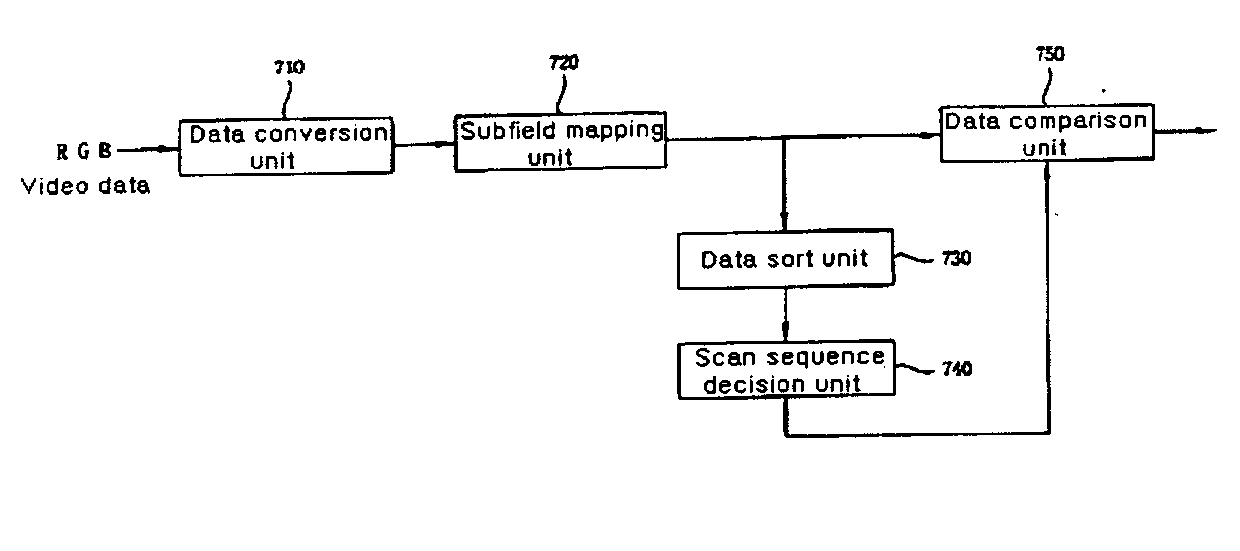
The present invention relates to an apparatus and method for driving a plasma display panel, and more particularly, to a scan drive apparatus and method of a plasma display panel. The present invention includes a data conversion unit converting video data to converted video data suitable for the PDP, a subfield mapping unit mapping a subfield corresponding to the converted video data, a data comparison unit computing a size of a displacement current by comparing video data of a cell bundle including at least one cell situated on a specific scan line to video data of a cell bundle situated in vertical and horizontal directions of the cell bundle according to each scan type of a plurality of scan types, and a scan sequence decision unit deciding a scan sequence according to the scan type having a small displacement current inputted from the data comparison unit.

Description

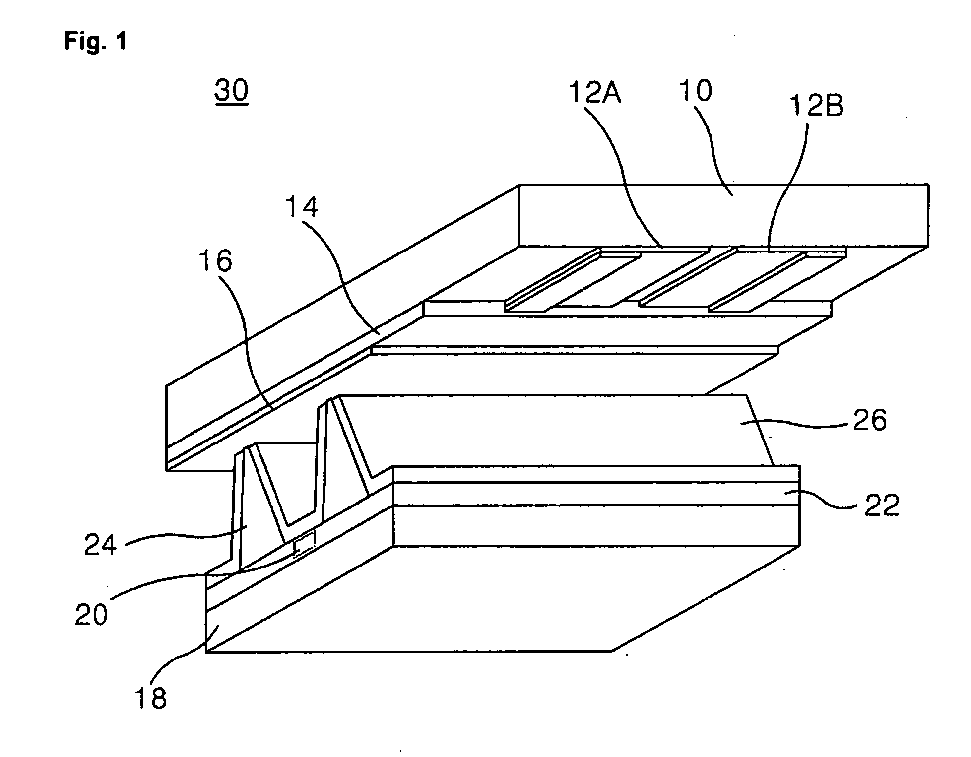
APPARATUS AND METHOD FOR DRIVING PLASMA DISPLAY PANEL [0001] This Nonprovisional application claims priority under 35 U.S.C. § 119(a) to patent application Ser. No. 10-2004-0056123 filed in Korea on Jul. 19, 2004, the entire contents of which are hereby incorporated by reference.BACKGROUND OF THE INVENTION [0002] 1. Field of the Invention [0003] The present invention relates to an apparatus and method for driving a plasma display panel, and more particularly, to a scan drive apparatus and method for a plasma display panel. [0004] 2. Description of the Background Art [0005] Generally, a plasma display panel (hereinafter abbreviated PDP) displays an image including characters and graphics by exciting a fluorescent substance using a 147 nm UV-ray emitted as a result of a mixed gas discharge involving (He+Xe) or (Ne+Xe). [0006]FIG. 1 is a perspective diagram of a PDP according to the related art. Referring to FIG. 1, the PDP consists of a Y-electrode 12A and a Z-electrode 12B formed on ...

Claims


Application Information

Patent Timeline
IPC IPC(8): G09G3/28G09G3/288G09G3/20G09G3/291G09G3/293G09G3/298
CPCG09G3/2051G09G3/28G09G3/296G09G2330/025G09G2310/0218G09G2310/0267G09G2330/021G09G2310/0213G09G2310/0286
Inventor TAKUYA, WATANABEKANG, SEONG HOYOON, SANG JINSIM, SOO SEOK
Owner LG ELECTRONICS INC
Why Eureka
Try Eureka