Image display system and method

a display system and image technology, applied in the field of image display systems and methods, can solve the problems of not being widely and practically used, not providing stereo images, and not being very convenient to operate, and achieve the effect of high cost of shooting and developmen

Inactive Publication Date: 2006-01-19
CULTURE COM TECH MACAU
View PDF3 Cites 18 Cited by
  • Summary
  • Abstract
  • Description
  • Claims
  • Application Information

AI Technical Summary

Benefits of technology

[0010] In light of the prior-art drawbacks, a primary objective of the present invention is to provide an image display system and method, for allowing users to see stereo images without requiring specific filters or polaroid glasses.
[0013] Compared with the conventional image display techniques, the image display system and method according to the present invention can provide a stereo image for users without concerning the high cost of shoot and development of stereo images and requiring specific filters or polaroid glasses.

Problems solved by technology

Although a photograph taken by the normal camera precisely records the size ratio and relative contrast and shading of object images and makes the images appear to be stereo, in fact the photograph does not provide stereo images if being seen at different directions or at broken pieces.
However, since the hologram requires irradiation of the specific light beam to produce the image and cannot be reproduced, it is thus not commonly and practically used.
Stereograph visible to naked eyes: the stereograph can be made by a simple method without the aid of any instrument, unlike the stereo images provided by the above methods that require the use of specific apparatuses and are not very convenient in operation.
As a result, the high cost of shoot and development of the stereo image, as well as the requirement of the special eyeglasses or change of the visual focal point, are a concern for users, thereby making stereo images not commonly used.

Method used


Image

  • Image display system and method
  • Image display system and method
  • Image display system and method

Examples


Embodiment Construction

[0017] In the following preferred embodiments provided for describing in detail an image display system and method proposed in the present invention, image data can be picture data, which may constitute static images or dynamic images composed of continuous static images. The picture data may comprise two similar pictures made by a parallax difference, or comprise RDS (random dot stereogram) made of random dots.

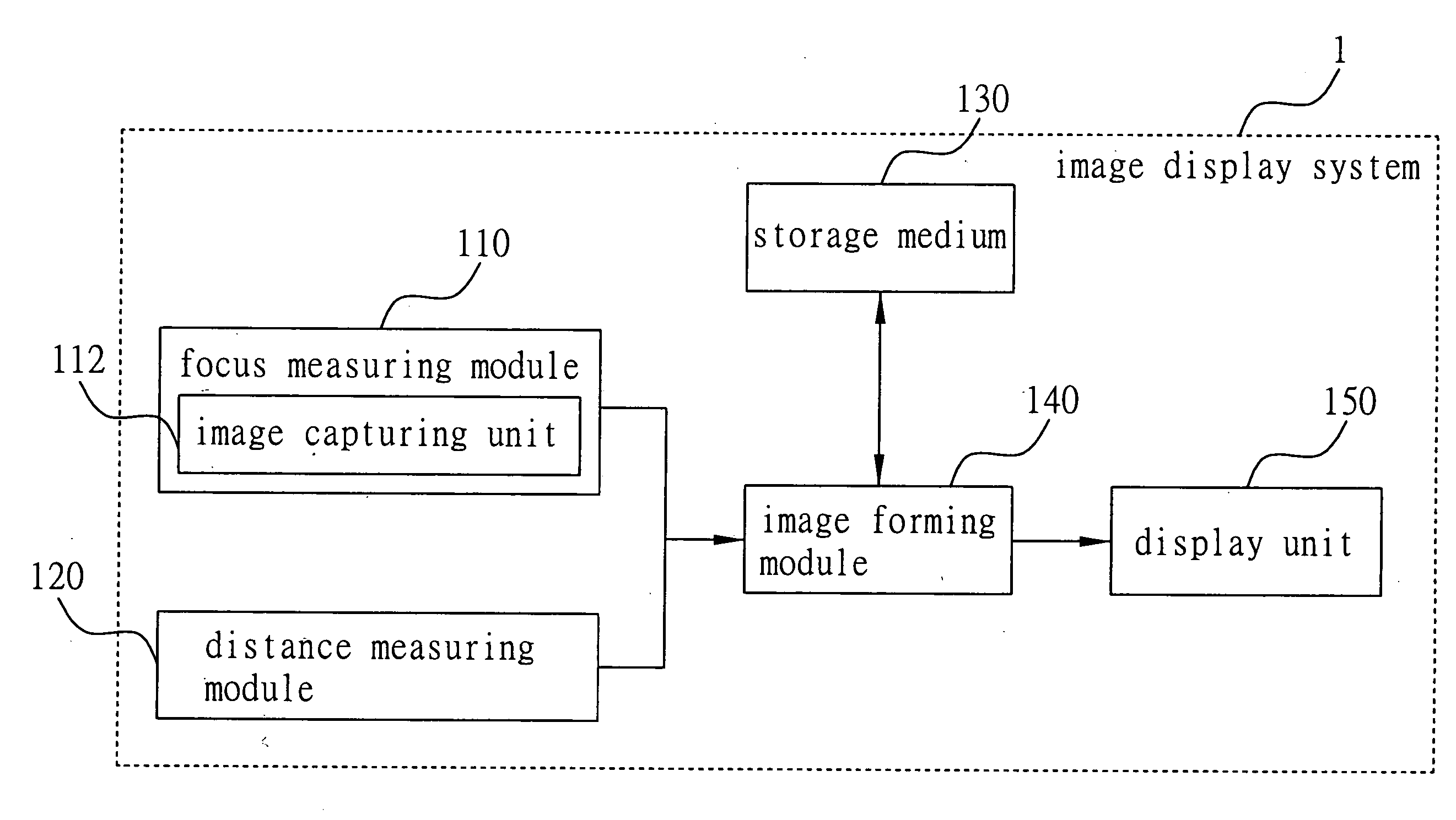
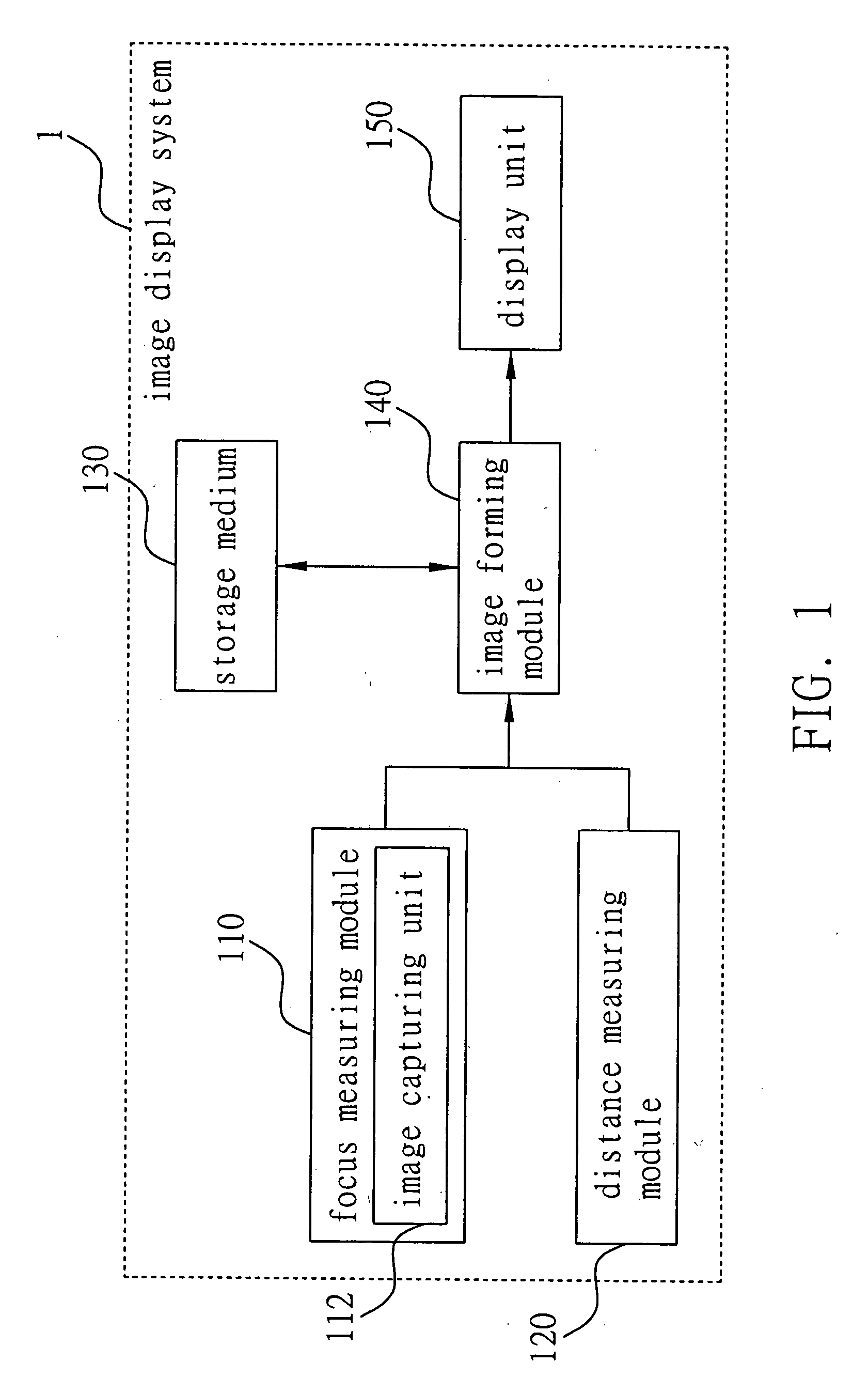
[0018] As shown in FIG. 1, the image display system 1 according to the present invention comprises: a focus measuring module 110; a distance measuring module 120; a storage medium 130; and an image forming module 140. Moreover, the image display system 1 is coupled with a display unit 150, e.g. a projector apparatus, for displaying the image data.

[0019] The focus measuring module 110 is used to immediately measure a focal point of a user's eyes. In this embodiment, the focus measuring module 110 comprises at least one image capturing unit 112, such as a CCD (charge-coupled ...


PUM


Abstract

An image display system and a method thereof are provided. A focal point of a user's eyes is measured by a focus measuring module. A distance between the user's eyes and a display unit is measured by a distance measuring module. At least two parallax image data are retrieved from a storage medium by an image forming module, and a distance between the at least two parallax image data is adjusted by the image forming module based on the focal point of the user's eyes and the distance between the eyes and the display unit, so as to display the adjusted parallax image data on an imaging point of the display unit. By the above system and method, a stereo image can be provided on the display unit without adjusting the focal point of the user.

Description

FIELD OF THE INVENTION [0001] The present invention relates to image display systems and methods, and more particularly, to a system and a method for displaying stereo images. BACKGROUND OF THE INVENTION [0002] An image formed on the retina of a single human eye is only provided at a planar vision. Since the two human eyes are located on the same plane, the eyes can see the same object at the same time. Due to small mismatch in locations and vision angles of the two human eyes, images captured by the left eye and the right eye are slightly different in parallax from each other, and such images are integrated by the brain to produce a stereo image. [0003] As described above, a real object can be identified and realized as a stereo image by the human eyes. However, the image of a real object captured and recorded in a tape or negative of an image capturing apparatus, e.g. a camera or video camera, would only be reproduced as a planar image. People may recognize what stereo object it r...

Claims


Application Information

Patent Timeline
Patent Type & Authority Applications(United States)
IPC IPC(8): H04N13/04H04N15/00
CPCH04N13/302H04N13/373
Inventor KAO, CHUNG-LUN
Owner CULTURE COM TECH MACAU
Why Eureka
Try Eureka