Temporal decomposition and inverse temporal decomposition methods for video encoding and decoding and video encoder and decoder

Inactive Publication Date: 2006-01-19
SAMSUNG ELECTRONICS CO LTD
View PDF2 Cites 62 Cited by
  • Summary
  • Abstract
  • Description
  • Claims
  • Application Information

AI Technical Summary

Benefits of technology

[0029] According to another aspect of the present invention, there is provided a video encoding method including downsampling a video frame to generate a low-resolution video frame, encoding the low-resolution video frame, and encoding the video frame using information about the encoded low-resolution video frame as a reference, wherein temporal decomposition in the encoding of the video frame comprises estimating motion of the video frame using at least one frame as a reference and generating a predicted frame, smoothing the predicted frame and generating a smoothed predicted frame, and generating a residual frame by comparing the smoothed predicted frame with the video frame.
[0030] According to another aspect of the present invention, there is provided a video decoding method including rec

Problems solved by technology

Conventional text communication cannot satisfy users' various demands, and thus multimedia services that can provide various types of information such as text, pictures, and music have increased.
These methods have satisfactory compression rates, but they do not have the flexibility of a truly scalable bitstream since they use a reflexive approach in a main algorithm.
However, currently known scalable video coding schemes offer significantly lower compression efficiency than other existing coding schemes such as H.264.
The low compression efficiency is an important factor that severely impedes the wide use of scalab

Method used


Image

  • Temporal decomposition and inverse temporal decomposition methods for video encoding and decoding and video encoder and decoder
  • Temporal decomposition and inverse temporal decomposition methods for video encoding and decoding and video encoder and decoder
  • Temporal decomposition and inverse temporal decomposition methods for video encoding and decoding and video encoder and decoder

Examples


first embodiment

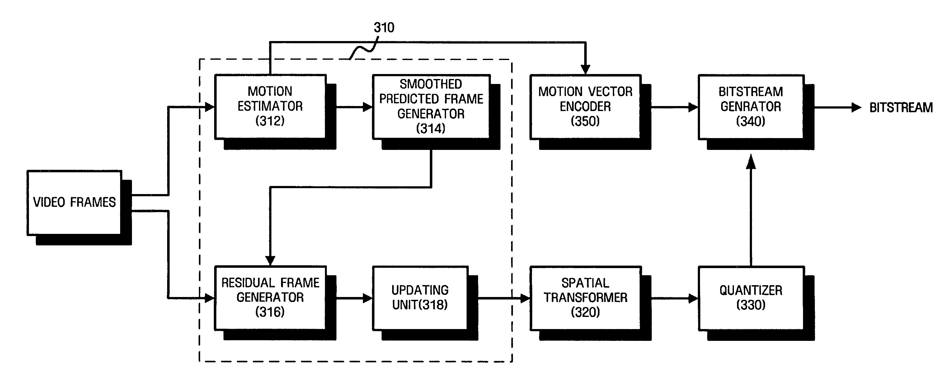
[0045]FIG. 3 is a block diagram of a video encoder according to the present invention.

[0046] Although a conventional motion-compensated temporal filtering (MCTF)-based video coding scheme requires an update step, many video coding schemes not including update steps have recently been developed. While FIG. 3 shows a video encoder performing an update step, the video encoder may skip the update step.

[0047] Referring to FIG. 3, the video encoder according to a first embodiment of the present invention includes a temporal decomposition unit 310, a spatial transformer 320, a quantizer 330, and a bitstream generator 340.

[0048] The temporal decomposition unit 310 performs MCTF on input video frames on a group of picture (GOP) basis to remove temporal redundancies within the video frames. To accomplish this function, the temporal decomposition unit 310 includes a motion estimator 312 estimating motion, a smoothed predicted frame generator 314 generating a smoothed predicted frame using mo...

second embodiment

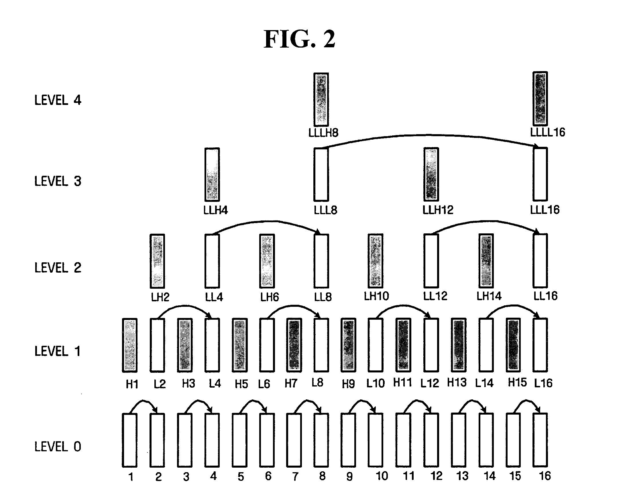
[0065]FIG. 5 illustrates a temporal decomposition process not including an update step according to the present invention.

[0066] Like in the first embodiment illustrated in FIG. 4, referring to FIG. 5, a video encoder obtains residual frames 2H, 4H, 6H, and 8H in level 1 using frames 1 through 8 in level 0 through a predicted frame generation process, a smoothing process, and a residual frame generation process. However, a difference from the first embodiment is that the frames 1, 3, 5, and 7 in level 0 are used as frames 1, 3, 5, and 7 in level 1, respectively, without being updated.

[0067] Through a predicted frame generation process, a smoothing process, and a residual frame generation process, the video encoder obtains frames 1 and 5 and residual frames 3H and 7H in level 2 using the frames 1, 3, 5, and 7 in level 1. Likewise, the video encoder obtains a frame 1 and a residual frame 5H in level 3 using the frames 1 and 5 in level 2.

third embodiment

[0068]FIG. 6 illustrates a temporal decomposition process using a Haar filter according to the present invention.

[0069] Like in the first embodiment shown in FIG. 4, a video decoder uses all processes, i.e., a predicted frame generation process, a smoothing process, a residual frame generation process, and an update process. However, the difference from the first embodiment is that a predicted frame is generated using only one frame as a reference. Thus, the video encoder can use either forward or backward prediction mode. That is, the encoder may not select a different prediction mode for each block (e.g., forward prediction for one block and backward prediction for another block) nor a bi-directional prediction mode.

[0070] In the present embodiment, the video encoder uses a frame 1 as a reference to generate a predicted frame 2P, smoothes the predicted frame 2P to obtain a smoothed predicted frame 2S, and compares the smoothed predicted frame 2S with a frame 2 to generate a resid...


PUM


Abstract

Temporal decomposition and inverse temporal decomposition methods using smoothed predicted frames for video encoding and decoding and video encoder and decoder are provided. The temporal decomposition method for video encoding includes estimating the motion of a current frame using at least one frame as a reference and generating a predicted frame, smoothing the predicted frame and generating a smoothed predicted frame, and generating a residual frame by comparing the smoothed predicted frame with the current frame.

Description

CROSS-REFERENCE TO RELATED APPLICATIONS [0001] This application claims priorities from Korean Patent Application No. 10-2004-0058268 filed on Jul. 26, 2004 in the Korean Intellectual Property Office, Korean Patent Application No. 10-2004-0096458 filed on Nov. 23, 2004 in the Korean Intellectual Property Office, and U.S. Provisional Patent Application No. 60 / 588,039 filed on Jul. 15, 2004 in the United States Patent and Trademark Office, the disclosures of which are incorporated herein by reference in their entirety. BACKGROUND OF THE INVENTION [0002] 1. Field of the Invention [0003] The present invention relates to video coding, and more particularly, to a method for improving image quality and efficiency for video coding using a smoothed predicted frame. [0004] 2. Description of the Related Art [0005] With the development of information communication technology including the Internet, video communication as well as text and voice communication has explosively increased. Conventiona...

Claims


Application Information

Patent Timeline
IPC IPC(8): H04N11/02H04N11/04H04N7/12H04B1/66H04N19/577
CPCH04N19/159H04N19/176H04N19/13H04N19/63H04N19/615H04N19/117H04N19/137H04N19/86H04N19/61H04N19/577
Inventor LEE, JAE-YOUNGHAN, WOO-JIN
Owner SAMSUNG ELECTRONICS CO LTD
Why Eureka
Try Eureka