
Method and system for reduction of noise in microphone signals

Inactive Publication Date: 2006-01-19
GOLDIN ALEXANDER
View PDF5 Cites 56 Cited by
  • Summary
  • Abstract
  • Description
  • Claims
  • Application Information

AI Technical Summary

Benefits of technology

[0022] Accordingly, the main object of this invention is to provide a method and a system for reduction of noise in microphone signals, said method and system of the invention possessing the following advantageous features:
[0027] e) minimal distortions of the signal of interest irrespective to the level of the noise or interfering sound.
[0049] The adapting means is advantageously configured to keep any of the filter coefficients nonnegative, when functioning in the far talk operative mode, and / or to restrict the sum of absolute values of the filter coefficients not to exceed a predetermined value, when functioning in the close talk operative mode. The purpose of the constraints employed in each operative mode is to preserve the signal of interest while reducing the interfering signals.

Problems solved by technology

It means that noise, echoes, room reverberation and other interferences can significantly degrade quality of signals recorded by such microphones.
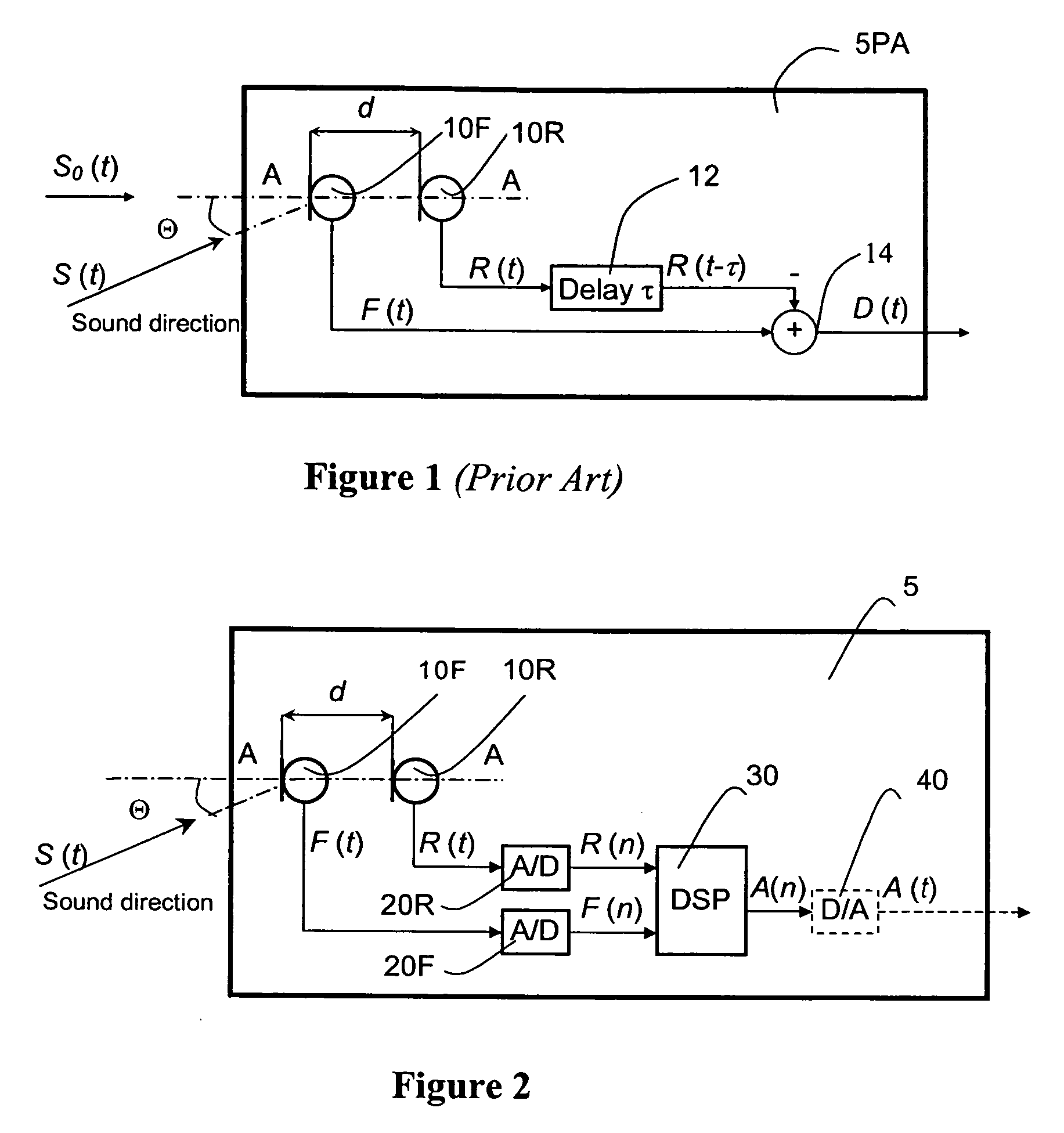
However, even with this addition, noise reduction effectiveness of the simple directional microphone of FIG. 1 is limited in many important respects.
Thus, in this case uniform delay in the whole frequency range does not allow to achieve the maximal possible SNR improvement.
A problem with such normalization arises, when short time RMS values of sound pressure levels on the two microphones 10 are not equal.
Another example of insufficiency of the described normalization is wind turbulences, when short time RMS values of sound pressure levels on the two microphones fluctuate independently.
A further problem arises in cases of a mismatch between sensitivities of two microphones serving as parts of the described directional microphone.

Method used


Image

  • Method and system for reduction of noise in microphone signals
  • Method and system for reduction of noise in microphone signals
  • Method and system for reduction of noise in microphone signals

Examples


Embodiment Construction

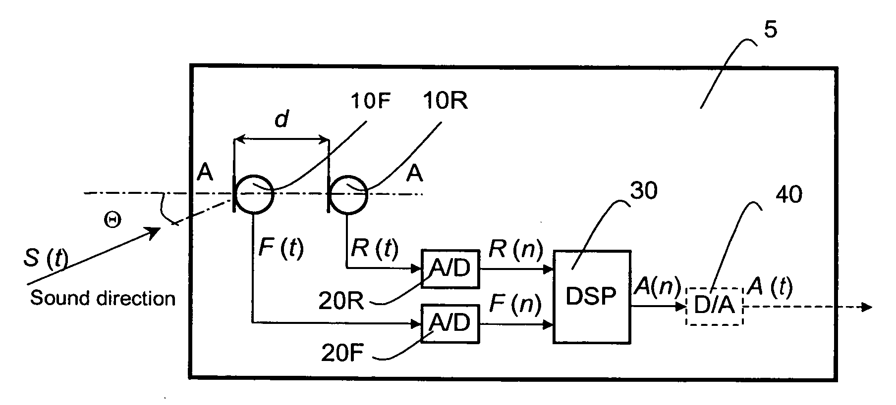
[0070]FIG. 2 shows the general scheme of the first embodiment of the noise reduction system according to the invention. The system of the invention is implemented as an improved autodirective dual microphone system of the general type shown in FIG. 1. Similarly to the prior art system, the proposed autodirective dual microphone system comprises two spatially distant microphones 10, a front microphone 10F and a rear microphone 10R.

[0071] The front microphone 10F and the rear microphone 10R are connected correspondingly to a front input channel and a rear input channel, each of said channels being represented by an analog-to-digital converter (ADC) 20F, 20R. When the microphones 10F, 10R receive acoustic signals, they correspondingly produce, in response to sound pressure changes, a front microphone signal F(t) and a rear microphone signal R(t), said signals F(t), R(t) being continuous analog electric signals. On receiving signals F(t), R(t), the analog-to-digital converters 20F, 20R...


PUM


Abstract

A method for processing noisy electric signals, particularly microphone signals, to produce a processed noise reduced signal, is disclosed. Noise reduction is effected by subtracting from a main (front) digital signal a filtered rear signal obtained through an application of continuously adaptable filter coefficients to a rear digital signal. The filter coefficients are supplied by adapting means configured to impose optimal selective constraints on said coefficients, depending on a selected operative mode (either a far talk mode or a close talk mode). According to preferred embodiments of the method, each of the front and rear digital signals is split into a number of frequency subband signals. Each pair of signals belonging to the same subband is processed separately, all processed subband signals being combined into a single noise-reduced output signal. A system for implementing various embodiments of the proposed method is also disclosed.

Description

BACKGROUND OF THE INVENTION [0001] 1. Field of the Invention [0002] This invention relates generally to the fields of directional microphones, microphone arrays, noise reduction and sound enhancement. [0003] 2. Description of the Related Art [0004] Widely used omnidirectional microphones pick up sounds (including various interferences) coming from different directions equally well. It means that noise, echoes, room reverberation and other interferences can significantly degrade quality of signals recorded by such microphones. In order to improve a signal-to-noise ratio (that is a ratio between levels of a useful signal and interfering signals picked up by a microphone), a wide range of means for reduction of noise in microphone signals has been developed. [0005] One of the simplest and widely used approaches to improve the signal-to-noise ratio (SNR) for microphone signals is represented by directional microphones. The directional microphones attenuate sounds coming from particular ...

Claims


Application Information

Patent Timeline
IPC IPC(8): H04B15/00H04R3/00
CPCH04R3/005H04R2499/11H04R2410/07H04R2201/403
Inventor GOLDIN, ALEXANDER
Owner GOLDIN ALEXANDER
Learn More