Polarisation-dependent optical fibre amplifier

a polarisation-dependent optical fiber and amplifier technology, applied in the direction of lasers, instruments, active medium shape and construction, etc., can solve the problems of high power level, high cost of reliable polarising optics, unreliable, etc., and achieve the effect of high power level and convenient configuration

Inactive Publication Date: 2006-01-19
SPI LASERS UK
View PDF2 Cites 18 Cited by
  • Summary
  • Abstract
  • Description
  • Claims
  • Application Information

AI Technical Summary

Benefits of technology

[0009] An advantage of the invention is that the apparatus can be readily configured to provide a single polarised mode from a fibre laser, and can do so at high power levels. This is particularly important when the output from the laser is to be processed by other devices such as frequency converters or phase modulators.
[0011] The gain medium may comprise one or more rare-earth dopants.
[0012] The rare earth dopant may comprise one or more of Ytterbium, Erbium, Neodymium, Praseodymium, Thulium, Samarium, Holmium, Europium, Terbium, and Dysprosium.
[0013] At least one of the fundamental modes, the first second-order modes, and the second second-order modes may be leaky at the operating wavelength.
[0014] The optical fibre is preferably configured to operate as a single-polarisation optical fibre at the operating wavelength.
[0015] The optical fibre may be tapered along its length.

Problems solved by technology

Although polarisation-maintaining fibres exist, these do not necessarily provide a single polarisation output, particularly at high powers where reliable polarising optics can be expensive, unreliable, and difficult to procure.
Stimulated Brillouin scattering provides a limitation for high-power fibre lasers and optical amplifiers.

Method used


Image

  • Polarisation-dependent optical fibre amplifier
  • Polarisation-dependent optical fibre amplifier
  • Polarisation-dependent optical fibre amplifier

Examples


Embodiment Construction

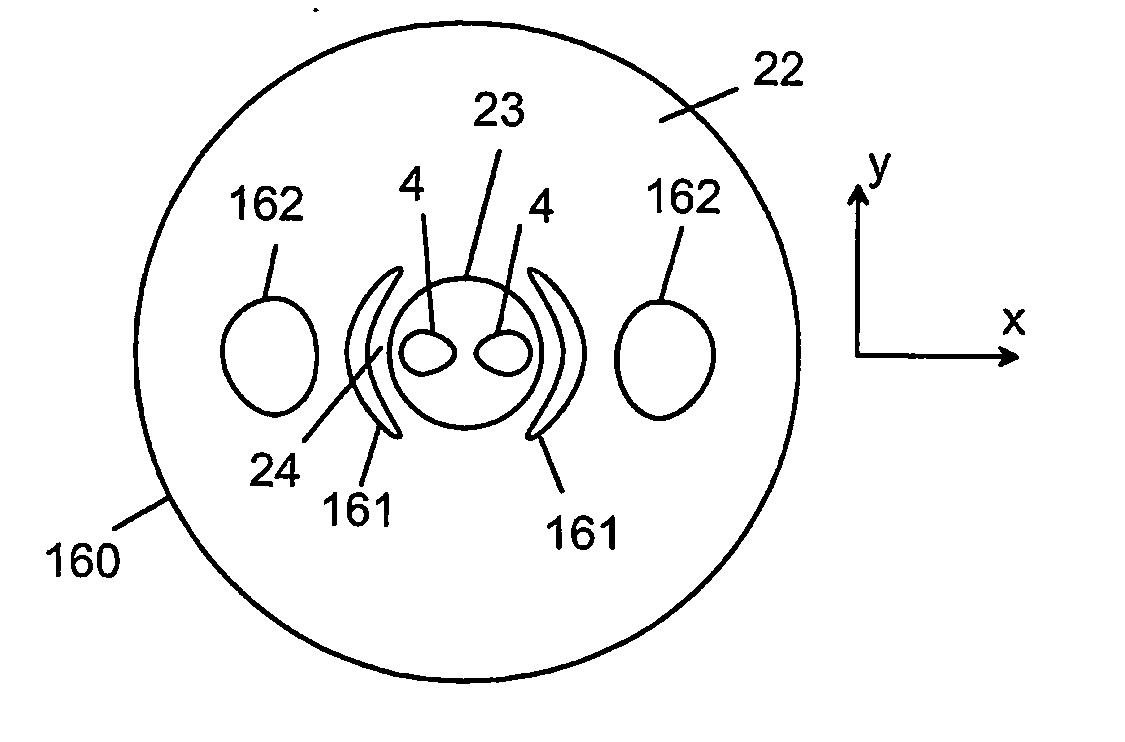
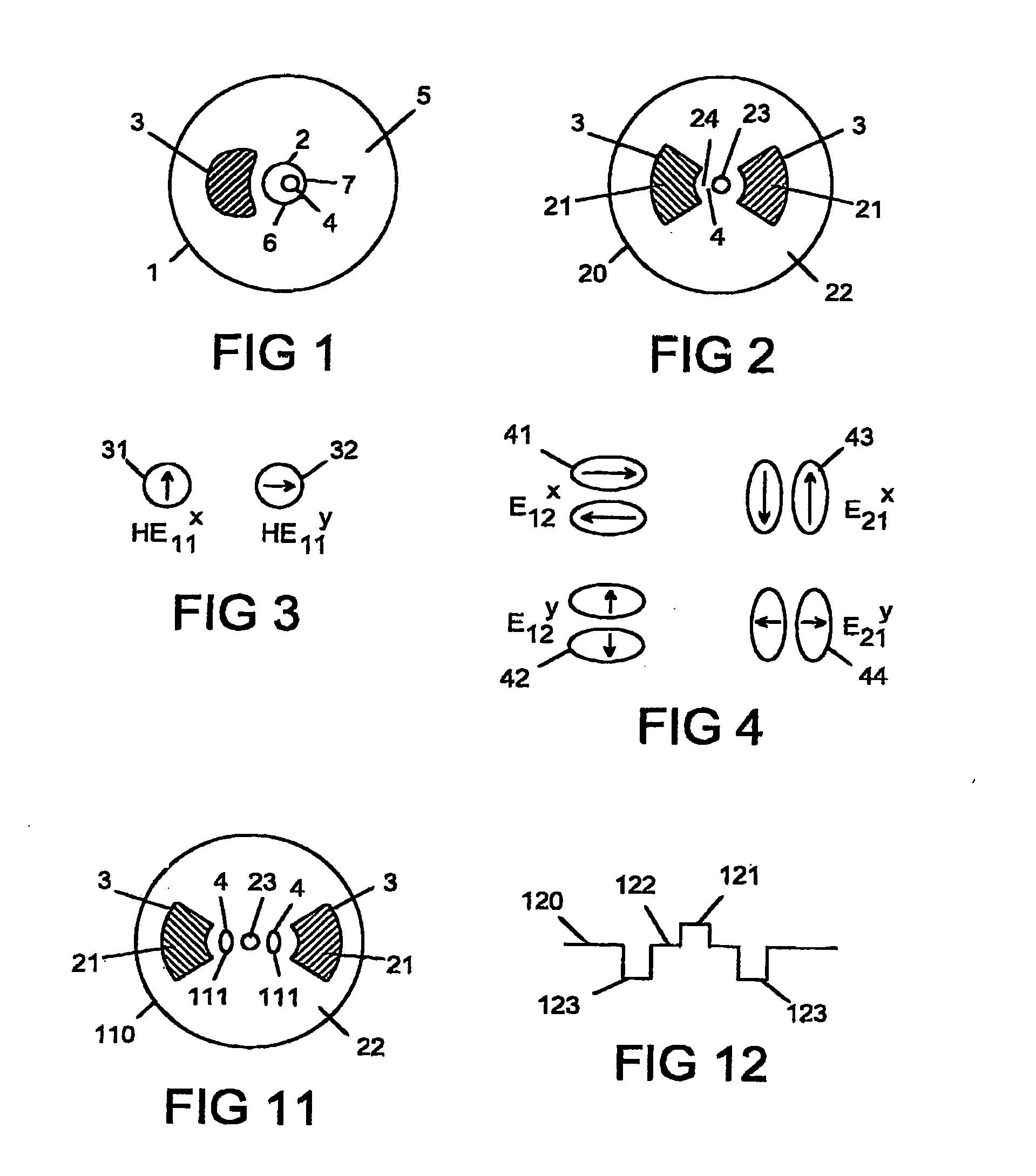
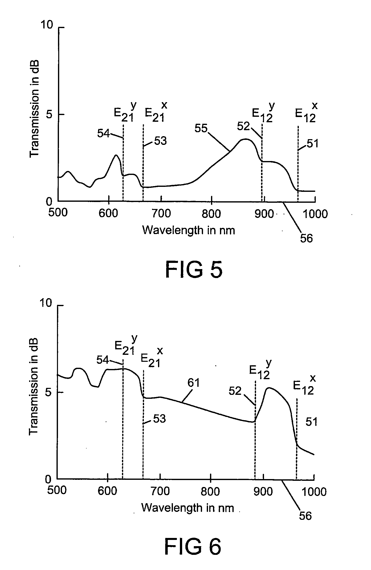
[0049] With reference to FIG. 1, there is provided apparatus comprising an optical fibre 1 having a waveguide 2 and at least one stress applying region 3: in which the waveguide 2 is defined by a numerical aperture 6; the stress applying region 3 has a depressed refractive index; the optical fibre 1 is configured such that the waveguide 2 supports at least two polarised fundamental modes, two polarised first second-order modes, and two polarised second second-order modes; the waveguide 2 comprises a gain medium 4; and the stress applying region 3, the waveguide 2 and the disposition of the gain medium 4 are such as to provide preferential guidance to at least one of the modes at an operating wavelength. The modes are shown below in FIGS. 3 and 4 as mode as numbers 31, 32, 41, 42, 43 and 44.

[0050] By depressed refractive index, it is meant that the refractive index of the stress applying region 3 is less than the average refractive index of the cladding 5.

[0051] The numerical apert...


PUM


Abstract

Apparatus comprising an optical fibre (1) having a waveguide (2) and at least one stress applying region (3): in which the waveguide (2) is defined by a numerical aperture; the stress applying region (3) has a depressed refractive index; the optical fibre (1) is configured such that the waveguide (2) supports at least two polarised fundamental modes, two polarised first second-order modes, and two polarised second second-order modes; the waveguide (2) comprises a gain medium (4); and the stress applying region (3), the waveguide (2)and the disposition of the gain medium (4) are such as to provide preferential guidance to at least one of the modes at an operating wavelength.

Description

CROSS REFERENCE TO RELATED APPLICATIONS [0001] The present application is a U.S. National Stage filing of Patent Cooperation Treaty (“PCT”) application serial number PCT / GB2003 / 004088, filed 24 Sep. 2003 (International Filing Date), which in turn claims priority to United Kingdom (Great Britain) Patent Application Serial Number GB0222252.9, filed 25 Sep. 2002.FIELD OF INVENTION [0002] This invention relates to apparatus comprising an optical fibre. The apparatus may form the basis of high-power lasers and amplifiers. BACKGROUND TO THE INVENTION [0003] Many applications of optical fibres required control of either polarisation or the mode shape. Particular examples are found in high-power fibre lasers and amplifiers whose optical output is further processed by polarisation-dependent devices such as modulators and frequency converters. Although polarisation-maintaining fibres exist, these do not necessarily provide a single polarisation output, particularly at high powers where reliab...

Claims


Application Information

Patent Timeline
Patent Type & Authority Applications(United States)
IPC IPC(8): G02B6/02G02B6/024H01S3/067
CPCG02B6/02314H01S3/06712H01S3/06708G02B6/024
Inventor VARNHAM, MALCOLM PAULTURNER, PAUL WILLIAMZERVAS, MIKHAIL NICKOLAOS
Owner SPI LASERS UK
Why Eureka
Try Eureka