Bandwidth limited frequency shift keying modulation format

a frequency shift and modulation format technology, applied in electromagnetic transmission, electrical equipment, transmission, etc., can solve the problems of modulated optical signals, limit the data rate and the span length of signals that can pass without signal regeneration, and achieve high costs

Inactive Publication Date: 2006-01-19
ALCATEL LUCENT SAS
View PDF4 Cites 10 Cited by
  • Summary
  • Abstract
  • Description
  • Claims
  • Application Information

AI Technical Summary

Benefits of technology

[0014] In view of the above, it is an object of the present invention to provide a method for processing optical signals showing re

Problems solved by technology

Due to dispersion and other physical effects in the optical fiber, the modulated optical signal is subjected

Method used


Image

  • Bandwidth limited frequency shift keying modulation format
  • Bandwidth limited frequency shift keying modulation format
  • Bandwidth limited frequency shift keying modulation format

Examples


Embodiment Construction

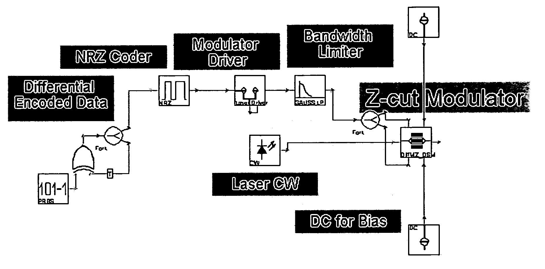
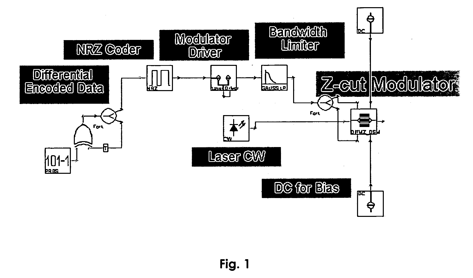
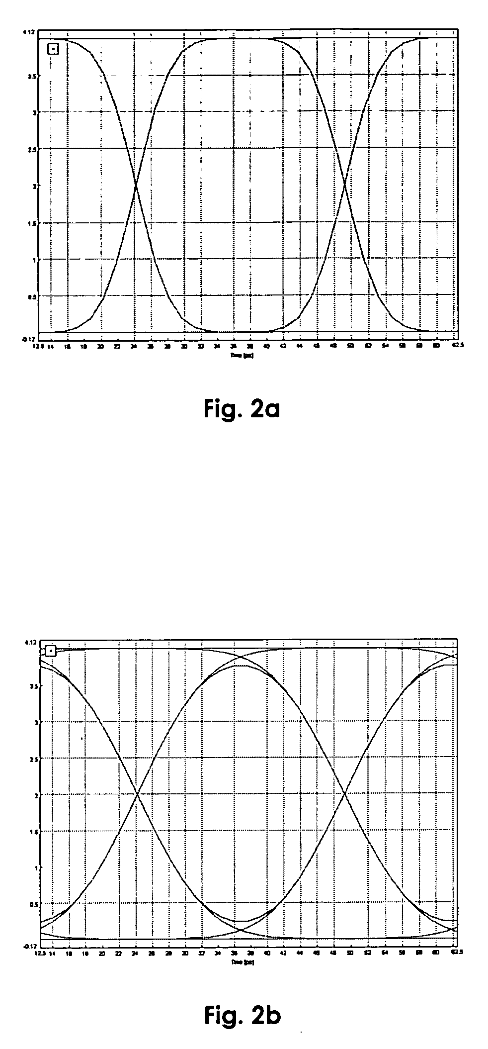
[0029] The invention is based on using a band limited differential pre-coded data signal to drive a phase modulator (for example a push-push Mach-Zehnder modulator with the same data signal for both electrodes). The limited electrical bandwidth of the electrical and opto-electronic components (modulator driver and modulator) produces a ramp-signal instead of a stair-case data signal. The ramp-signal is maximal for an electrical bandwidth half of the bit rate (Electrical Bandwidth ˜B / 2). Such ramp data signal is used to modulate the CW emission of a loser. The result is a frequency modulation of the optical carrier so that the one of the two bit states (here “0” state) have the same frequency as the carrier and the other state (here “1” state) have ±Δf frequency. The frequency deviation Δf can be flexibly varied by varying the amplitude of the electrical data signal applied to the modulator.

[0030] The optical spectrums of the “0s” and “1s” are limited to B (the Bit rate bandwidth) a...


PUM


Abstract

It is an object of the present invention to provide a method for processing optical signals showing real improvement for the transmission of optical signals over long distance at high bit rate but without implying to high costs. This is achieved by the use of a new modulation format (BL-FSK) based on the generation of a frequency modulated signal. It is obtained by driving an electro-optical modulator (e.g. LiNbO3) with a 1-bit delay pre-coded signal (or some other differential pre-coding) in a similar way as for generating DPSK. But unlike for DPSK, it is advantageously make use of the bandwidth limitation of the electrical and electro-optical components, chosen close to a half of the bit rate (B). A ramp-electrical signal is generated that produces the FSK modulation. As a direct consequence of such modulation, a higher spectral efficiency and a lower cost construction of the transmitter is achieved.

Description

TECHNICAL FIELD [0001] The present invention relates to a method for processing optical signals to be transmitted through an optical transmission line using optical pulse stream with a Frequency Shift Keying format. The invention is based on a priority application EP 04 291 830.0 which is hereby incorporated by reference. BACKGROUND OF THE INVENTION [0002] For long-haul optical signal transmission, information to be transmitted is modulated onto an optical carrier signal and transmitted over an optical fiber link. Due to dispersion and other physical effects in the optical fiber, the modulated optical signal is subjected to distortion that limits the data rate and the span length the signal can pass without signal regeneration. [0003] Currently, next generation transmission systems using bitrates in the range of 40 Gbit / s—in particular 42.6 Gbit / s—are being developed. The development of cost-effective 43 Gbit / s transmission systems, however, requires comprehensive evaluations of mod...

Claims


Application Information

Patent Timeline
IPC IPC(8): H04B10/04H04B10/12H04B10/50H04B10/556
CPCH04B10/505H04B10/5563H04B10/5055
Inventor LAZARO VILLA, JOSE ANTONIOIDLER, WILFRIED
Owner ALCATEL LUCENT SAS
Why Eureka
Try Eureka