Electrical power generator

a technology of electric power generators and batteries, applied in the direction of electrochemical generators, cell components, cell component details, etc., can solve the problem of limited energy capacity of lithium batteries, for a given weight of batteries,

Active Publication Date: 2006-01-19
HONEYWELL INT INC
View PDF5 Cites 57 Cited by
  • Summary
  • Abstract
  • Description
  • Claims
  • Application Information

AI Technical Summary

Problems solved by technology

However, the energy capability of lithium batteries, for a given weight of the battery, is limited.

Method used


Image

  • Electrical power generator
  • Electrical power generator
  • Electrical power generator

Examples


Embodiment Construction

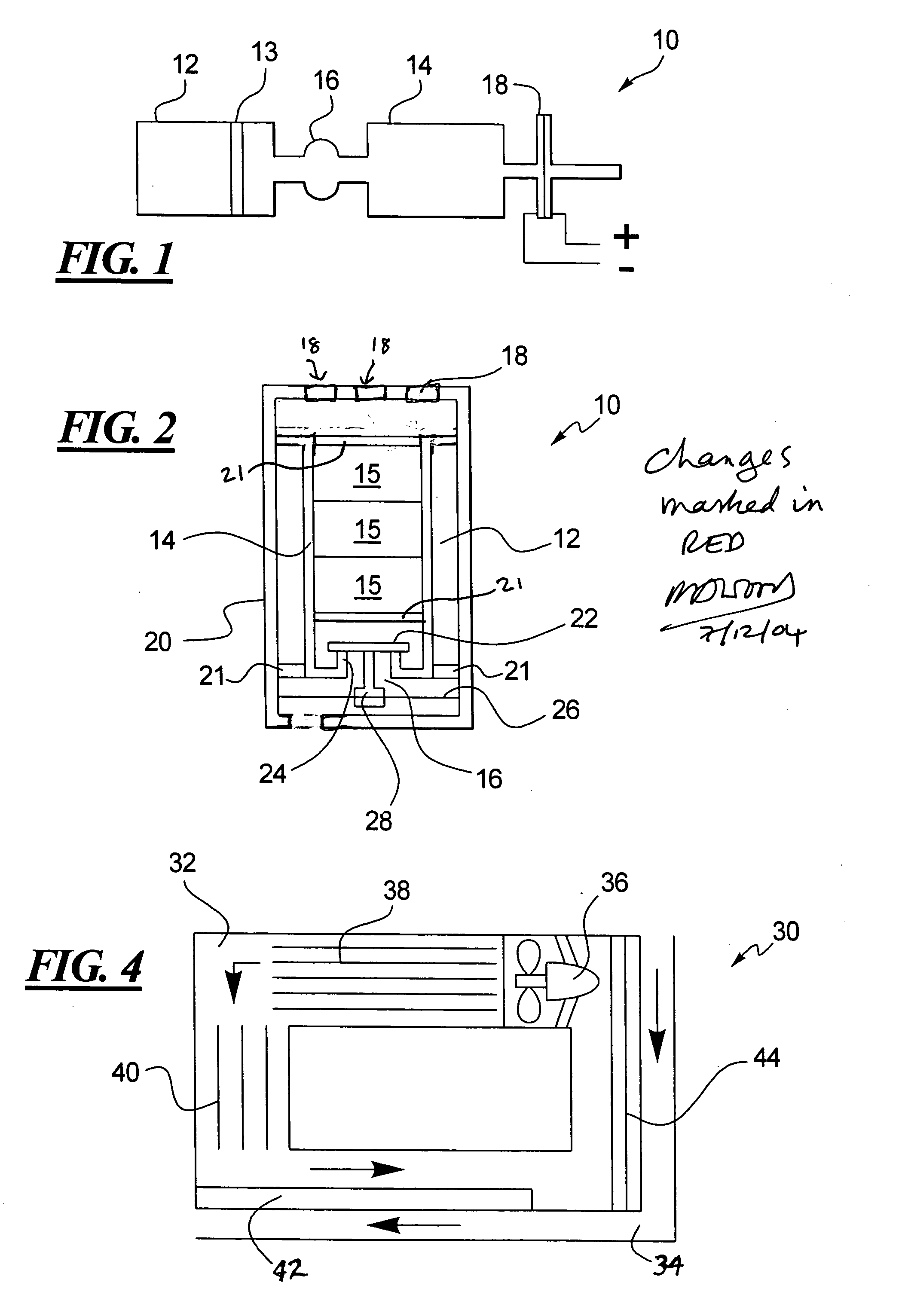
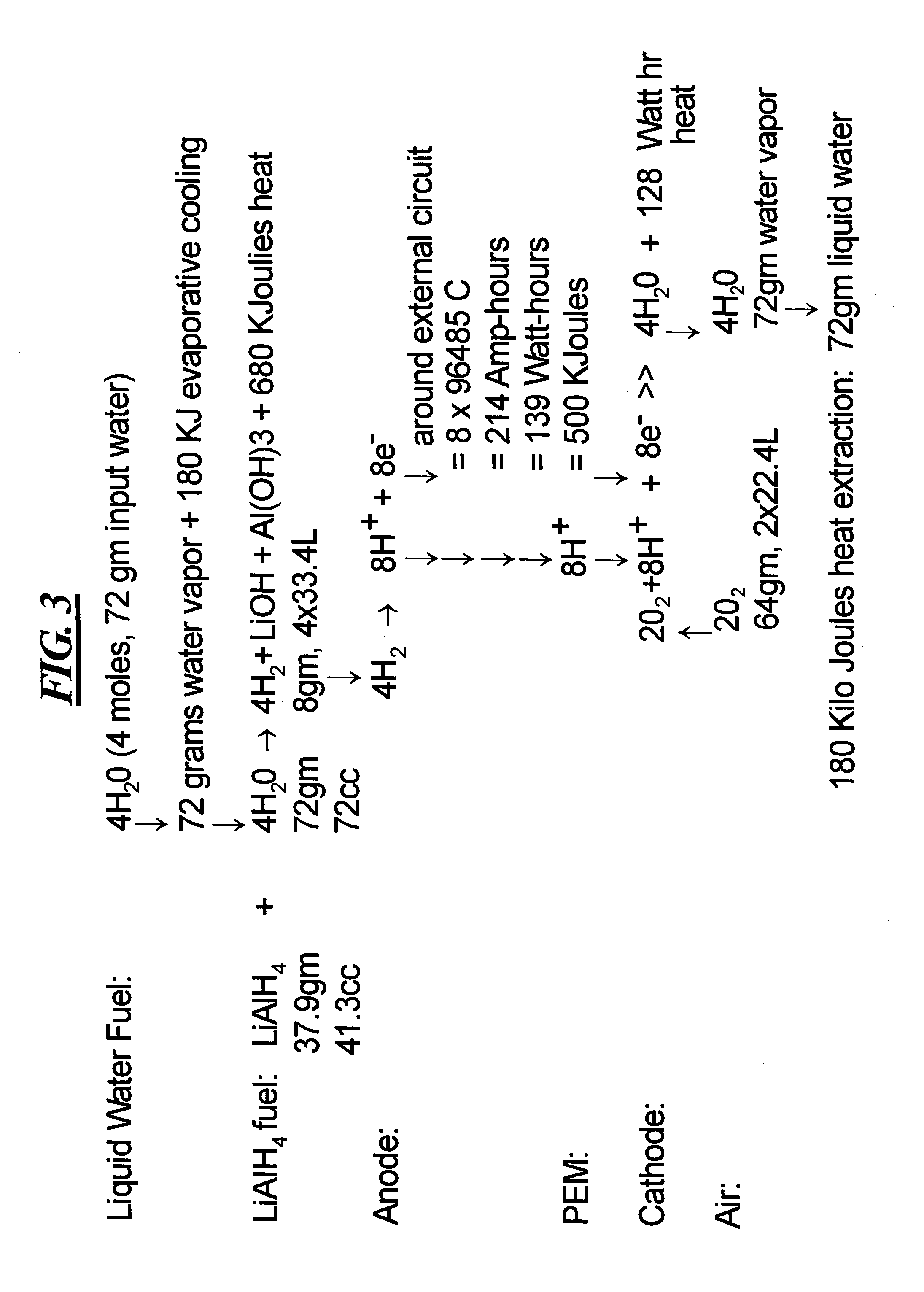
[0022] The micropower source 10 discussed above is extremely simple and efficient for mW level power generation. However, the micropower source 10 employs a slow natural evaporation and diffusion rate of moisture from its water reservoir 12, that significantly limits power generation. Moreover, the water that is produce by the fuel cells 18 is exhausted as waste, which limits the smallest size ands weight of the fuel required by the micropower source 10. As can be seen from the chemical reaction sequence of FIG. 3, in principle it is not necessary to re-supply water to the micropower source 10 because the natural action of the fuel cells 18 produces water at exactly the rate required by the chemical reaction between the water vapor and the fuel.

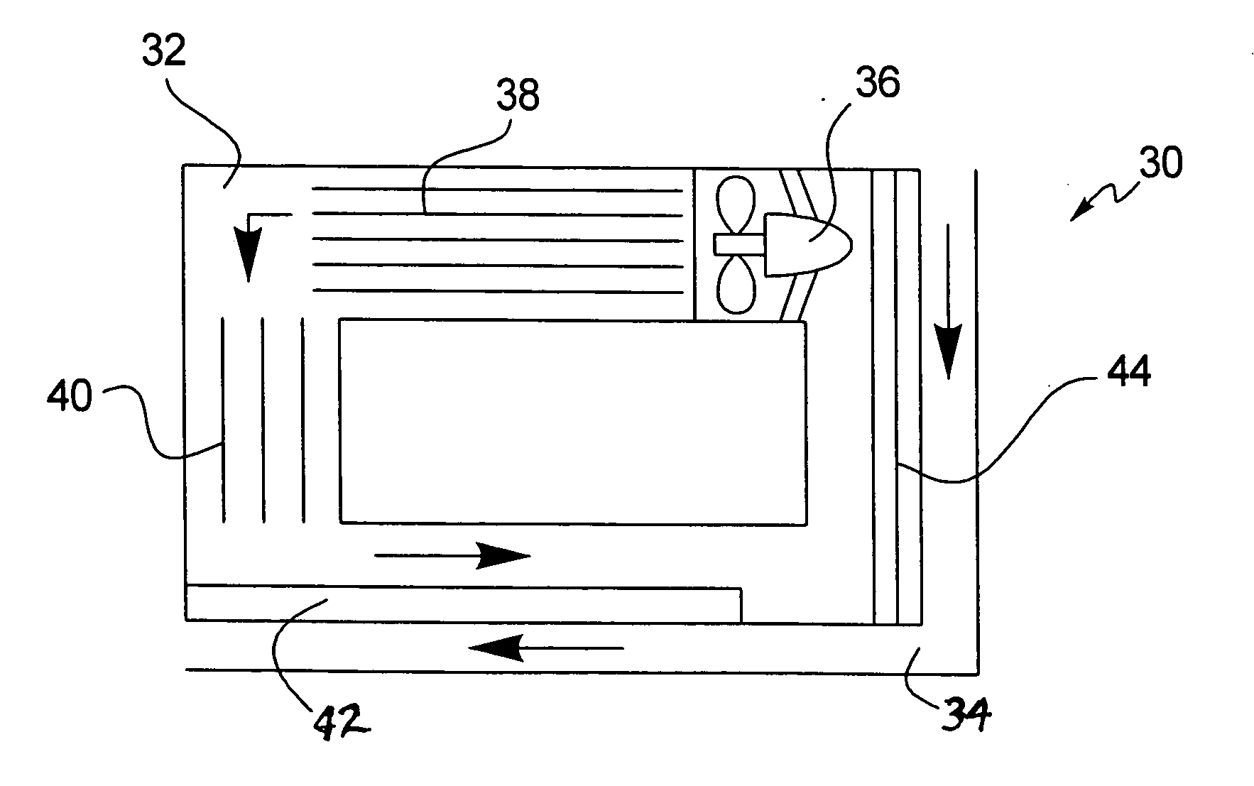
[0023]FIG. 4 shows a closed-cycle micropower source 30 in accordance with one embodiment of the present invention. The closed-cycle micropower source 30 includes a hydrogen flow path 32 and a humid air flow path 34. A flow inducer 36 such as...


PUM

PropertyMeasurementUnit
diameteraaaaaaaaaa
RHaaaaaaaaaa
poweraaaaaaaaaa

Abstract

A power generator has a hydrogen flow path through which moisture is induced to flow to a hydrogen-containing fuel that reacts with the moisture to produce hydrogen. The moisture passes to the hydrogen flow path through a water exchange membrane from a water vapor flow path. A fuel cell between the hydrogen flow path and the water vapor flow path reacts with the hydrogen in the hydrogen flow path to produce electricity, and to also principally produce the moisture in the water vapor flow path.

Description

TECHNICAL FIELD OF THE INVENTION [0001] The present invention relates to electrical power generators. BACKGROUND OF THE INVENTION [0002] There is an ongoing but urgent need for lighter weight sources of electricity for many applications, such as battlefield applications, unmanned aircraft, and unattended wireless sensors. Presently, the power source that is primarily used is the lithium battery. However, the energy capability of lithium batteries, for a given weight of the battery, is limited. [0003] It is desirable to increase the power of electrical sources by many times, thus making it possible to materially increase the operating life of electronic equipment without adding weight. [0004] The assignee of the present invention has previously developed a high performance micropower source 10 shown in FIG. 1. The micropower source 10 includes a water reservoir 12, a water permeable membrane 13, a solid fuel reservoir 14, and a pneumatic valve 16. The water reservoir 12 may be arrang...

Claims


Application Information

Patent Timeline
Patent Type & Authority Applications(United States)
IPC IPC(8): H01M8/04H01M2/14
CPCC01B3/065H01M8/04007H01M8/04097H01M8/04126H01M8/04149Y02B90/18H01M8/065H01M2008/1095H01M2250/30Y02E60/362Y02E60/50H01M8/04164Y02B90/10Y02E60/36
Inventor WOOD, ROLAND A.
Owner HONEYWELL INT INC
Why Eureka
Try Eureka