
Apparatus and method for preparing bone for anti-rotational implantation of an orthopedic endoprosthesis

a technology of orthopedic endoprosthesis and bone preparation, which is applied in the field of apparatus and method for preparing bone for anti-rotational implantation of orthopedic endoprosthesis, can solve the problems of increasing intra-operative time, affecting the alignment of the bone, and affecting the quality of the bon

Active Publication Date: 2006-01-19
HOWMEDICA OSTEONICS CORP
View PDF35 Cites 31 Cited by
  • Summary
  • Abstract
  • Description
  • Claims
  • Application Information

AI Technical Summary

Benefits of technology

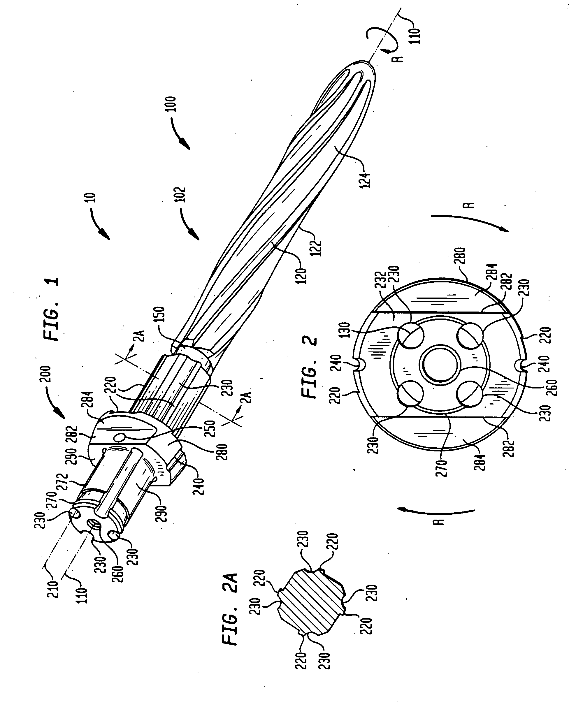
[0029] In the preferred embodiment, the grooves on the flange and the guide channels are preferably used in combination. The grooves are used to mark the surgical tool's orientation on the bone, and then the guide channels are used to form the keyways in the bone canal. Thereafter, the markings made by using the grooves help validate the correct positions of the keyways.
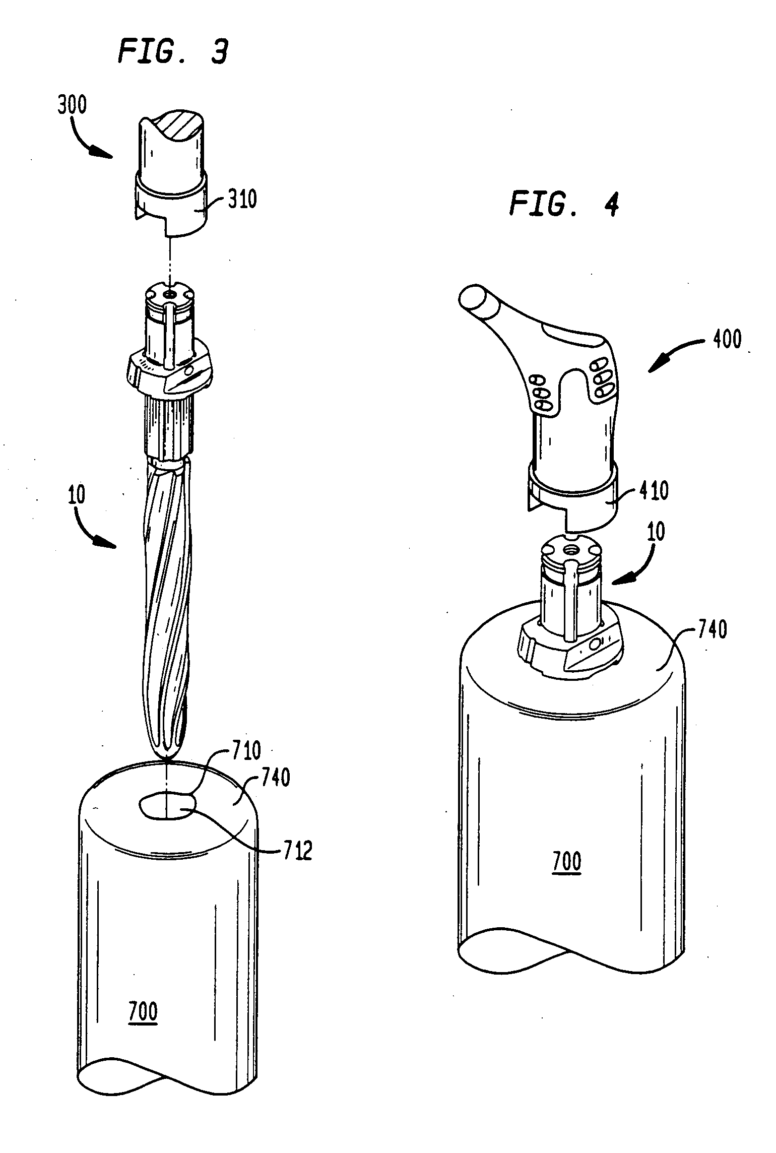
[0031] Once the anti-rotation channels are formed, the surgical tool is removed from the bone canal. The prepared bone canal then receives a prosthesis having a stem with anti-rotational components, such as keys, that align with the cut keyways, and help secure the prosthesis from rotating in the bone canal.

Problems solved by technology

Sometimes, the stem must be removed and reinserted, which may damage the bone cavity and surrounding bone, as well as increase intra-operative time.
The drawback to this method is the potential imprecision in the alignment.
Because the marks on the stem and bone are not in close proximity to each other, parallax and other problems associated with alignment by eye may result.
Misalignment of an implanted prosthesis in the human body is an undesirable result in joint replacement surgery.

Method used


Image

  • Apparatus and method for preparing bone for anti-rotational implantation of an orthopedic endoprosthesis
  • Apparatus and method for preparing bone for anti-rotational implantation of an orthopedic endoprosthesis
  • Apparatus and method for preparing bone for anti-rotational implantation of an orthopedic endoprosthesis

Examples


Embodiment Construction

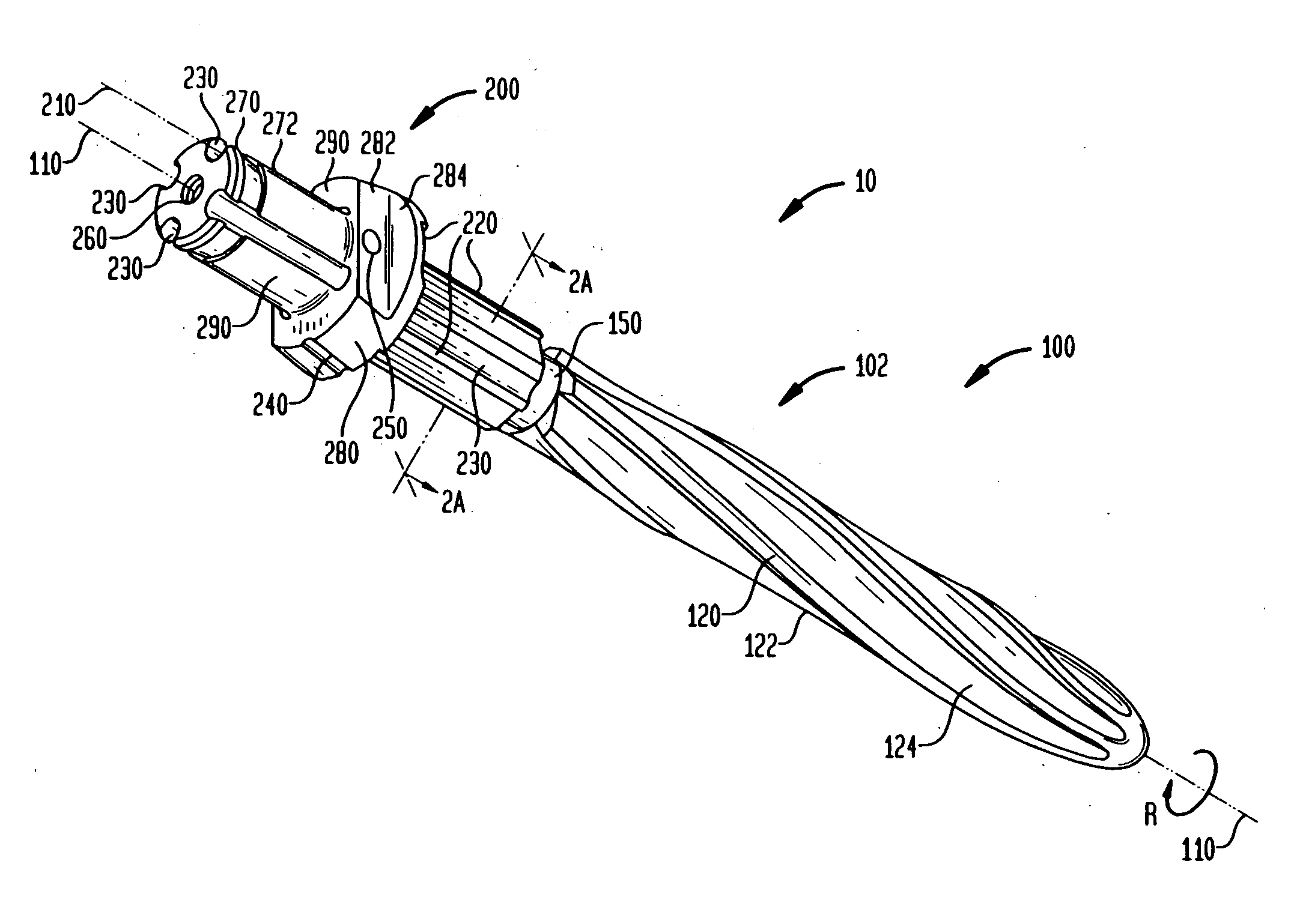
[0042] Referring to FIGS. 1 and 2, there is illustrated the surgical tool or instrument of the present invention, generally denoted as 10. In the preferred embodiment, instrument 10 has a first distal end 100 and a second proximal end 200 extending along longitudinal axis 110. First end 100 is in the form of a reamer 102 used to ream a bone canal in a long bone, while second end 200 has multiple applications including providing an attachment interface to various instruments, and providing elements facilitating marking and forming keyways in the bone. Both ends 100 and 200 of instrument 10 will be discussed in more detail, below.

[0043] With reference to FIGS. 1-3, in the preferred embodiment, reamer 102 has multiple spiraled cutting teeth 120 for reaming bone canal 710 to a desired diameter. Cutting teeth 120 form a circular cutting profile 130 that is perpendicular to longitudinal tool axis 110. Profile 130 is essentially the cutting perimeter of first end 100 of instrument 10. It ...


PUM


Abstract

An apparatus and method for reaming a bone, facilitating pre-implantation alignment of a prosthesis using trial components, and preparing a bone site for anti-rotational implantation of the prosthesis is provided. The apparatus includes a boring end, a mating end disposed opposite the boring end, and a keying aid disposed between the boring end and mating end. The keying aid facilitates preparation of the bone canal for anti-rotational placement of a prosthesis having an anti-rotational component, or key. The method includes attaching a power tool to the mating end of the apparatus, reaming a bone canal with the boring end of the apparatus, detaching the power tool, attaching a trial component, conducting alignment trials, maintaining the apparatus in the desired position, detaching the trial component, cutting at least one keyway in the bone canal using a cutting device and the keying aid of the apparatus, removing the cutting device, removing the apparatus from the reamed bone canal, and inserting the prosthesis into anti-rotational engagement with the reamed bone by aligning the key on the prosthesis with the keyway in the bone canal.

Description

CROSS-REFERENCE TO RELATED APPLICATIONS [0001] This application is a divisional of U.S. application Ser. No. 10 / 248,565, filed on Jan. 29, 2003, the disclosure of which is incorporated herein by reference.BACKGROUND OF THE INVENTION [0002] 1. Field of the Invention [0003] This invention relates to a surgical tool and method for preparing a bone site for implantation of an orthopedic endoprosthesis having anti-rotational components as well as facilitating pre-implantation alignment of the prosthesis. More particularly, the invention relates to aligning and implanting a femoral component of a total hip joint or a humeral component of a shoulder joint. However, it may also be used to align and implant femoral and tibial components of a prosthetic knee joint. [0004] The method and surgical tool that is used to open and form the bone canal also facilitates pre-implantation alignment of the prosthesis using trial components, as well as preparation of the bone site for anti-rotational impl...

Claims


Application Information

Patent Timeline
IPC IPC(8): A61B17/16
CPCA61B17/164A61B17/1684A61B17/1675A61B17/1668
Inventor MCGOVERN, MICHAEL A.
Owner HOWMEDICA OSTEONICS CORP
Learn More