Positioning system with cannulated implant

Inactive Publication Date: 2006-01-19
SMITH & NEPHEW INC +2
View PDF14 Cites 81 Cited by
  • Summary
  • Abstract
  • Description
  • Claims
  • Application Information

AI Technical Summary

Benefits of technology

[0006] The present invention relates to a positioning system for placing an implant into a cavity of a bone. In particular, the present invention enables the implant to be

Problems solved by technology

In both cases cited above, it is not possible to achieve a high precision when positioning the implan

Method used


Image

  • Positioning system with cannulated implant
  • Positioning system with cannulated implant
  • Positioning system with cannulated implant

Examples


Embodiment Construction

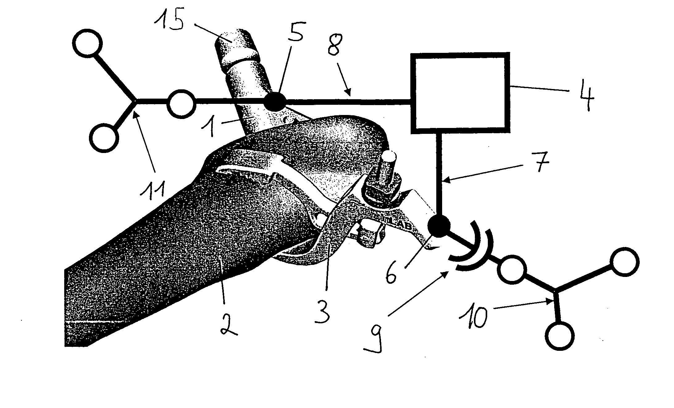
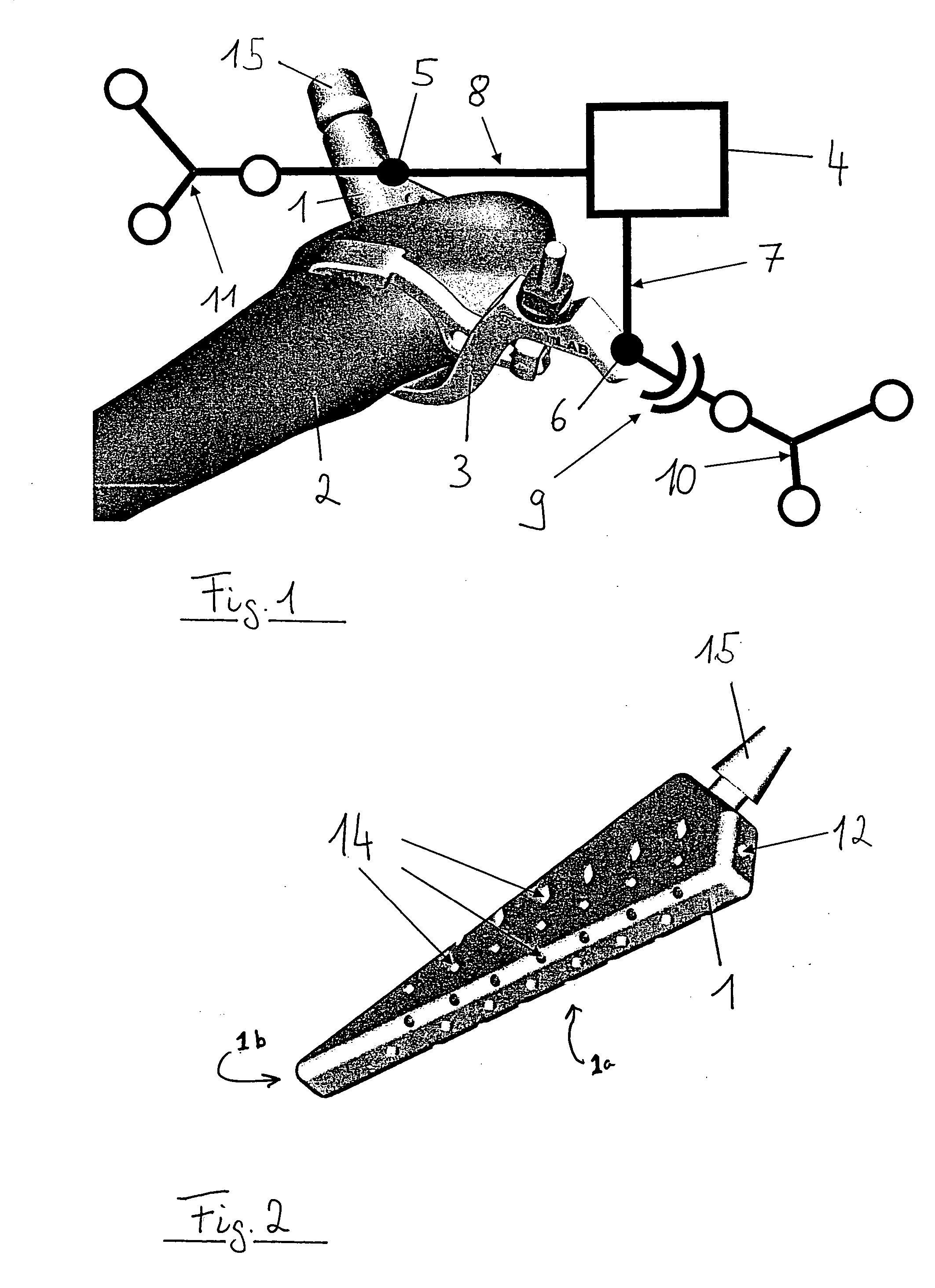
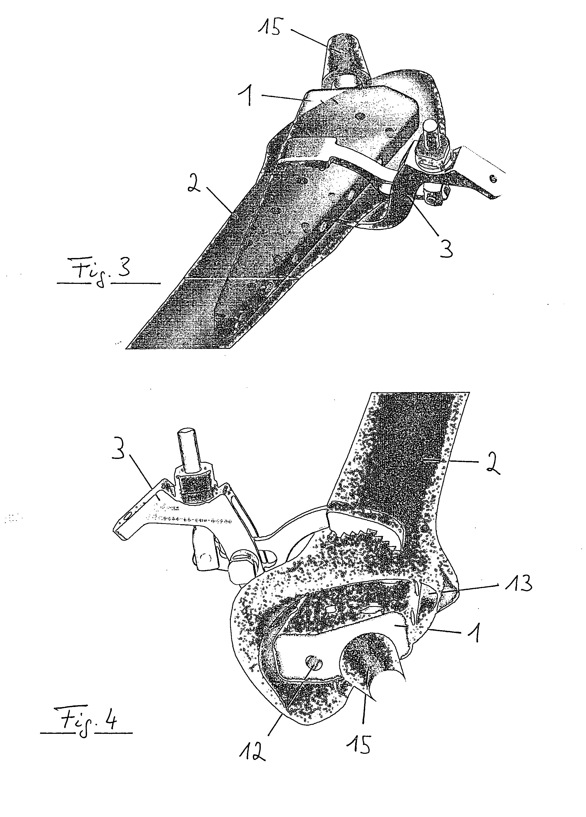
[0021] Identical parts are provided with identical reference numerals in the figures. In all the figures, the implant which may be used in accordance with the invention bears the reference numeral 1. The implant 1 is designed to be inserted into a cavity 13 (FIG. 4) of a femur 2 (FIGS. 1, 3 and 4), and is shown in more detail in FIG. 2. The implant 1 includes an implant body 1a tapering forward toward a distal end 1b and further including outlets 14 on its periphery for a fluid (filler, e.g., bone cement). Once the implant has been placed, the fluid is intended to fill the cavities between the implant 1 and the inner bone walls and fix the implant 1 with respect to the bone 2. The fluid is injected in via an inlet opening 12 of the implant 1, which is shown in FIGS. 2 and 4. An interface for receiving an implant head is indicated by the reference numeral 15. Embodiments in which the inlet opening leads through this interface are also conceivable.

[0022] In order to enable precise po...


PUM


Abstract

A positioning system for placing an implant into a cavity of a bone, comprising a cannulated implant that is substantially smaller in the implanting area than the cavity and a positioning device that can hold the implant in a settable position in the cavity.

Description

RELATED APPLICATION DATA [0001] This application claims priority of U.S. Provisional Application No. 60 / 590,221 filed on Jul. 22, 2004, which is hereby incorporated herein by reference in its entirety.FIELD OF THE INVENTION [0002] The present invention relates to a positioning system for placing an implant into a cavity of a bone. In particular, the present invention relates to a positioning system for a revision implant. BACKGROUND OF THE INVENTION [0003] Different procedures currently exist for placing implants or constructing a bone-like structure using cement and other fillers. In most cases, bone cement is poured into an open or exposed bone channel, for example a femoral cavity, once the old implant has been removed. This can be achieved with the aid of cannulated rods, or by introducing the cement into the bone cavity in some other way. Sample implants are sometimes used to form a mold in accordance with the actual implant, which then is introduced once the cement has hardene...

Claims


Application Information

Patent Timeline
IPC IPC(8): A61F2/34
CPCA61B2019/5483A61F2230/0019A61F2/3662A61F2/4607A61F2002/30153A61F2002/30785A61F2002/30787A61F2002/30789A61F2002/3625A61F2002/365A61F2002/368A61F2002/4632A61F2002/4688A61F2002/4696A61F2/36A61B2090/3983
Inventor PLASSKY, NORMANTUMA, GREGOR
Owner SMITH & NEPHEW INC
Why Eureka
Try Eureka