Prosthesis and method of implantation

Inactive Publication Date: 2006-01-19
THE JAMES B GRIMES & TRACIE LYNN GRIMES 1998 TRUST
View PDF6 Cites 91 Cited by
  • Summary
  • Abstract
  • Description
  • Claims
  • Application Information

AI Technical Summary

Benefits of technology

[0008] One aspect of the invention is directed to a bone prosthesis for implantation at a joint. The prosthesis comprises a stem sized and shaped for implantation in a bone at the joint, the stem having a proximal portion, a distal portion and a longitudinal axis extending therethrough. The distal

Problems solved by technology

Those portions subject to a lesser stress than before are likely to deteriorate and those subject to greater stress than before are likely to thicken.
But if the stress is too great and applied over an extended period, bone cells may be killed.
A disadvantage of “offset” alignment is that it creates a bending mome

Method used


Image

  • Prosthesis and method of implantation
  • Prosthesis and method of implantation
  • Prosthesis and method of implantation

Examples


Embodiment Construction

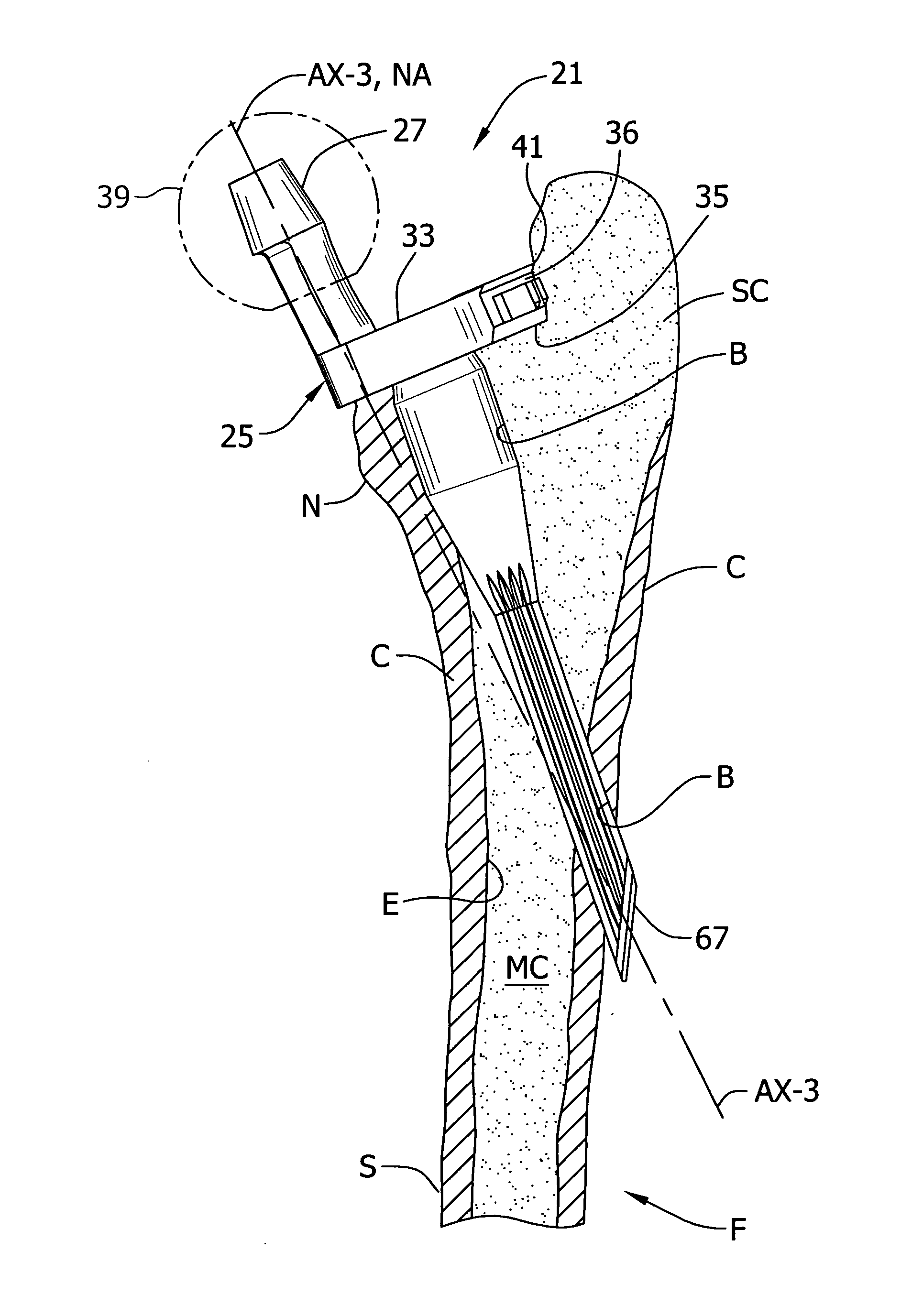
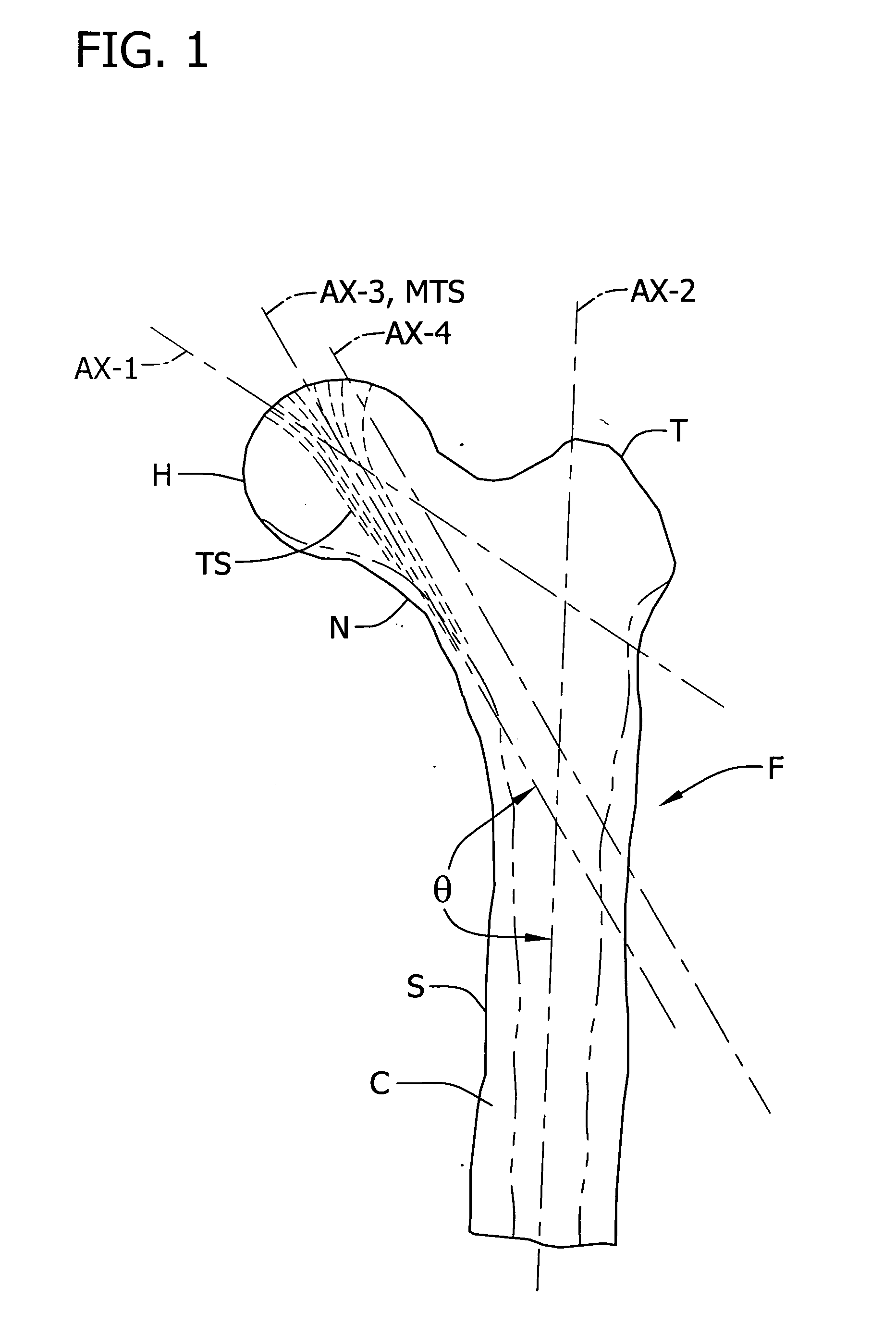
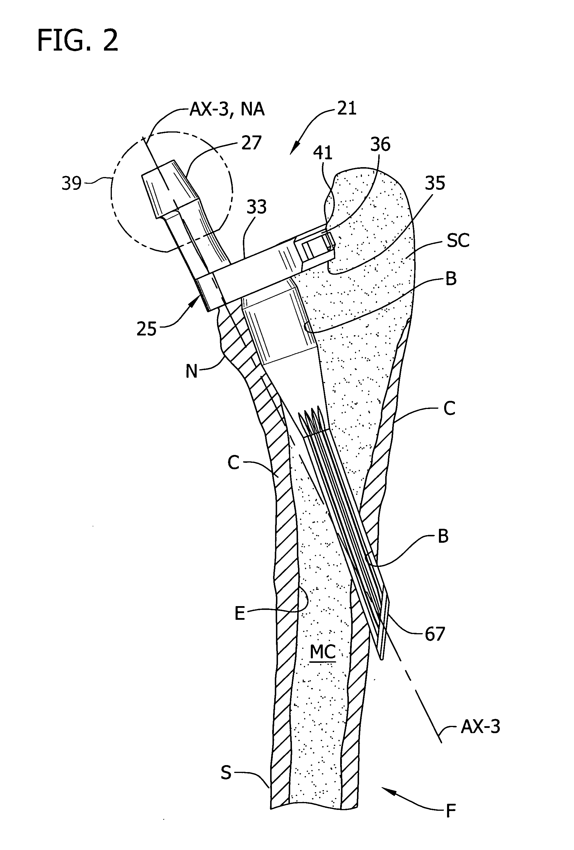
[0049] Referring now to the drawings and in particular to FIGS. 1-2, a transosseous prosthesis of an embodiment of the invention is designated in its entirety by the reference numeral 21. In this embodiment, the prosthesis is suitably sized and shaped for implantation in a femur F, though it is to be understood that the prosthesis may be sized and shaped for implantation in other bones, e.g., the humerus. The femur includes a femoral shaft S, a femoral head H (it is removed in FIG. 2), neck N, a trabecular stream TS and a greater trochanter T at the upper end of the shaft at the lateral side of the femur. The femur F has a hard layer of cortical bone C adjacent the surface of the bone, relatively soft cancellous bone SC, a medullary canal MC, and endosteum E inside the femur.

[0050] As implanted, the transosseous prosthesis 21 extends through a bore B generally from the resected femoral neck N diagonally across the medullary canal MC and out an opposite side of the femur. The prosth...


PUM

PropertyMeasurementUnit
Fractionaaaaaaaaaa
Fractionaaaaaaaaaa
Angleaaaaaaaaaa

Abstract

A bone prosthesis for implantation at a joint is adapted to closely replicate the normal loading of the femur and is suitable for implantation using a single incision anterior approach, a form of minimally invasive surgery (MIS). The bone prosthesis comprises a stem adapted for orientation with a medial trabecular stream of the femur.

Description

CROSS REFERENCE TO RELATED APPLICATION [0001] This application claims priority from Provisional Application Ser. No. 60 / 589,173 filed on Jul. 17, 2004, which is hereby incorporated by reference in its entirety.BACKGROUND [0002] The present invention relates to an implantable prosthesis for implantation in a bone such as a femur. [0003] A femoral head-neck prosthesis that fails to replicate normal loading conditions will change the stress distribution through the femur. As mentioned in U.S. Pat. No. 4,998,937, according to Wolff's law these changes in stress distribution eventually cause alterations in the internal structure of the bone. Those portions subject to a lesser stress than before are likely to deteriorate and those subject to greater stress than before are likely to thicken. But if the stress is too great and applied over an extended period, bone cells may be killed. [0004] As shown in FIG. 1, the human femur F has two externally visible axes: the axis of the femoral neck ...

Claims


Application Information

Patent Timeline
IPC IPC(8): A61F2/36A61F2/30A61B17/90
CPCA61B17/1668A61B2017/1778A61B17/175A61F2/30723A61F2/30767A61F2/3601A61F2/367A61F2/3676A61F2/4637A61F2/468A61F2002/2835A61F2002/30224A61F2002/30332A61F2002/30474A61F2002/30604A61F2002/30784A61F2002/30787A61F2002/30794A61F2002/30827A61F2002/30968A61F2002/3625A61F2002/3639A61F2002/3641A61F2002/3652A61F2002/3684A61F2002/3694A61F2002/4631A61F2002/4636A61F2220/0025A61F2220/0033A61F2230/0069A61F2310/00023A61F2310/00029A61F2310/00407A61F2310/00413A61B17/1684A61B17/1778A61F2002/30772A61F2002/3079A61F2002/3631A61F2002/368A61F2002/4635
Inventor GRIMES, JAMES B.
Owner THE JAMES B GRIMES & TRACIE LYNN GRIMES 1998 TRUST
Why Eureka
Try Eureka