Anchor bolt placement protection assembly and method for aligning structural elements in a form when pouring concrete

Inactive Publication Date: 2006-01-26
SMITH JAMES R
View PDF15 Cites 59 Cited by
  • Summary
  • Abstract
  • Description
  • Claims
  • Application Information

AI Technical Summary

Benefits of technology

[0009] Accordingly, it is an object of the present invention to provide an anchor bolt protection and support assembly that cooperates with the threaded end of the anchor bolt to properly position the anchor bolt and protect the anchor bolt during the pour. Proper position provides a precise spacing in relation to the inner surface of a form board and also provides an appropriate depth for the length of the bolt and t

Problems solved by technology

While it is expected that the bottom spacer bars will be of appropriate length to retain the bottom edges of the form boards at the appropriate spacing in the trench bottom where they can be held in place by the pressure of the dirt filled into the trench against the outside surfaces of the form, it has been discovered that the wooden cleats nailed across the top edges of the form board provided unsatisfactory results.
Often, the top edges of the form boards spread apart as the form is filled with concrete, and the spacing of the form boards is ruined.
This is caused by improper nailing of the top cleat.
This procedure is expensive in terms of materials and time since it often takes the workman a significant amount of time to achieve proper spacing at the top edges of the form boards.
Another disadvantage of this method of spacing and retaining the upper edges of the form boards is that frequently workmen are paid for the number of linear feed of forms they erect.
Workmen paid in this manner are motivated to work quickly rather than carefully and so contribute to the improper spacing of the top edges of the form boards or improper nailing of the cleats.
Another disadvantage is that during the concrete pour, as the form is filled, the cleats are an obstruction to the agitation of the concrete.
Placement of these anchor bolts is critical but the position of the anchor bolt is often misjudged, thus increasing the difficulty of boring holes in the mud sill to receive the anchor bolts.
In addition to misplacement or irregular spacing between successive anchor bolts, another problem in the prior art system of setting anchor

Method used


Image

  • Anchor bolt placement protection assembly and method for aligning structural elements in a form when pouring concrete
  • Anchor bolt placement protection assembly and method for aligning structural elements in a form when pouring concrete
  • Anchor bolt placement protection assembly and method for aligning structural elements in a form when pouring concrete

Examples


first embodiment

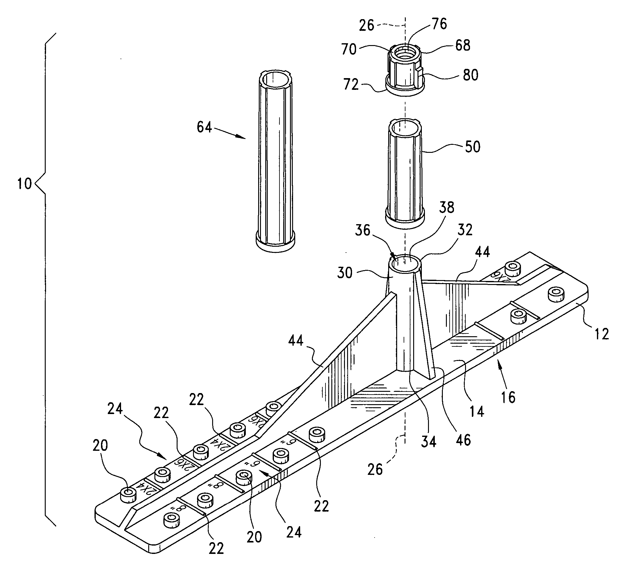
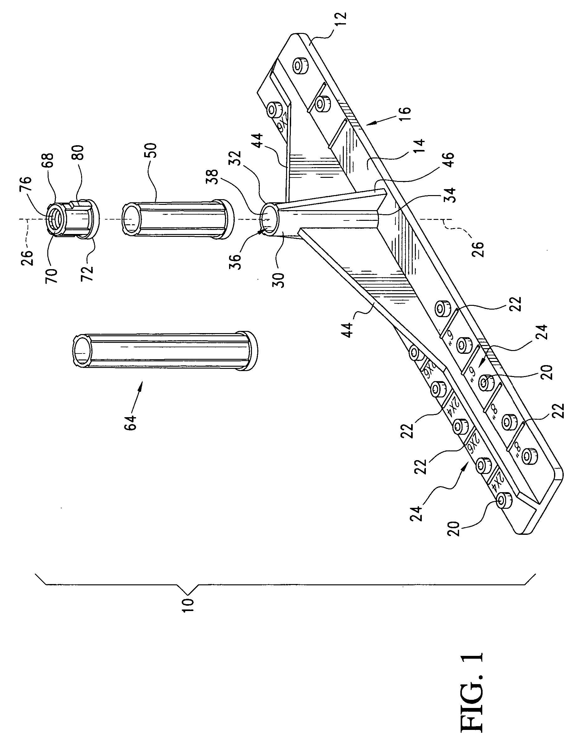
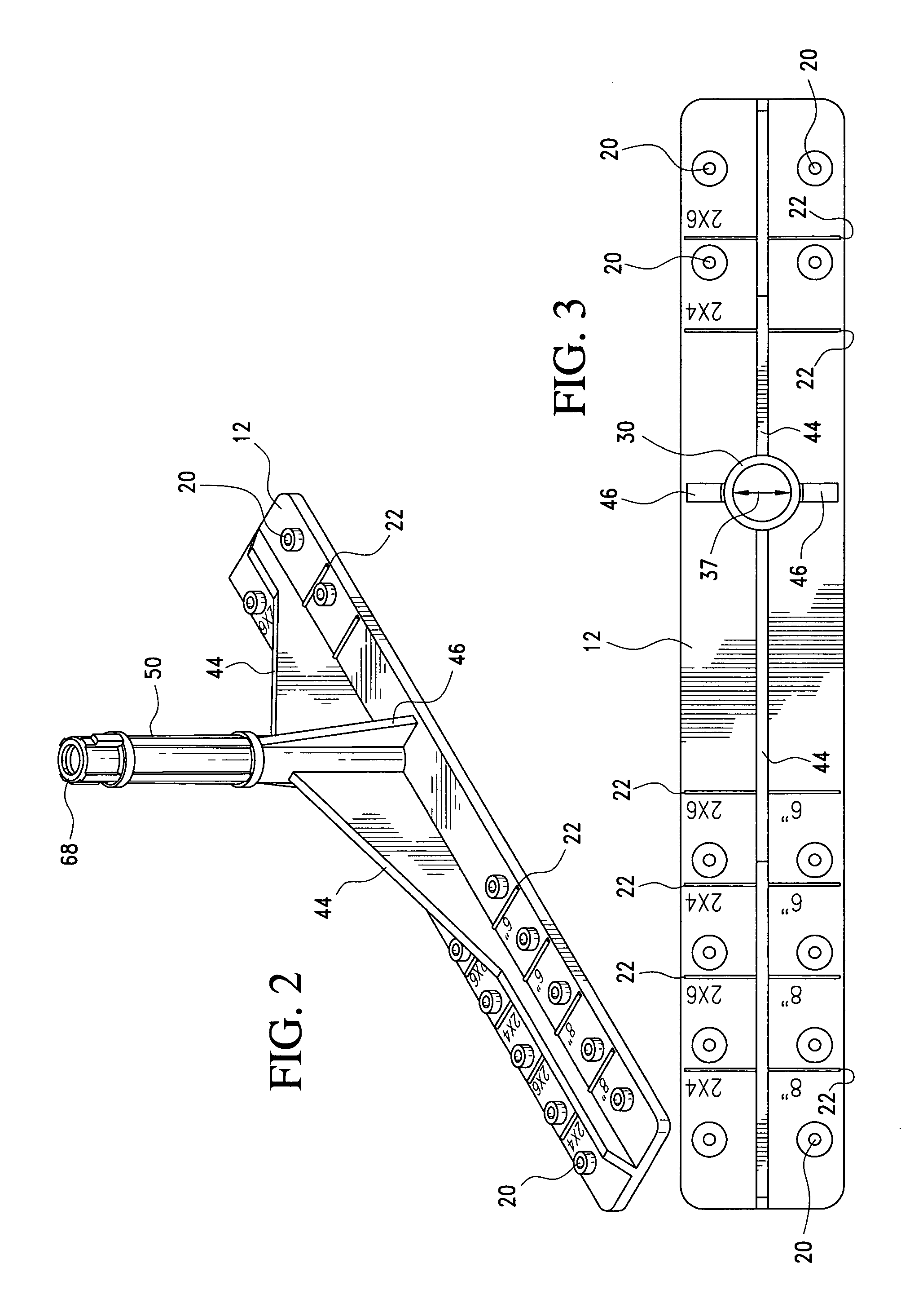
[0039] the anchor bolt placement and protection assembly 10 of the present invention is illustrated in FIGS. 1-5. Referring now to FIGS. 1 and 2, anchor bolt placement and protection assembly 10 includes a substantially planar base plate or flange 12 having an upper surface 14 opposite a lower surface 16. In the illustrated embodiment, a base plate bolt aperture 18 is provided in the shape of a circle. Base plate 12 also includes a plurality of nail-receiving apertures 20 each including a raised collar portion dimensioned to receive and hold a nail placed within the collar in preparation for having that nail driven into a foundation form board or the like. The nail apertures 20 are preferably spaced at even increments selected to appropriately position base plate 12 in relation to form boards during a pour (e.g., as seen in FIG. 6).

[0040] Base plate 12 also includes, on upper surface 14, a plurality of substantially parallel spaced, transverse alignment indicia ribs 22 which can be ...

second embodiment

[0050] Referring now to FIGS. 7 and 8, the anchor bolt placement and protection assembly 140 includes a substantially planar elongated base plate 142 from which projects a perpendicular tubular member 144. Base plate 142 is preferably configured as a rectangular member having a plurality of transverse thru-bores or apertures including a plurality of nail receiving apertures aligned with a plurality of alignment indicia or centering guide indicators. A longitudinal reinforcing web or rib 146 preferably supports fixed tubular member 144 which is also supported by a plurality of reinforcing ribs 148 that extend vertically along the length of tubular member 144. Tubular member 144 preferably has a selected diameter 150 which is slightly larger than and closely fits with a selected size of anchor bolt shaft.

[0051] Base plate 142 is a substantially rectangular member having radiussed corners, a length of approximately twelve inches, a width of approximately one and three sixteenth inches ...

third embodiment

[0052]FIGS. 9-11 illustrate the anchor bolt placement and protection assembly 160 including a substantially planar base plate 162 from which projects a substantially perpendicular cylindrical tubular member adapted to receive and sealably engage with one or more extension sleeves (e.g. 166, 170) or, optionally, a threaded nut 168 all of which have a selected inside diameter adapted to receive and protect an anchor bolt shaft of selected size. When configured as shown in FIG. 10, extension sleeve 166 has a proximal or lower flange area which sealably engages the distal sealing surface 164 of tubular member 164 to seal out debris, cement and other material which may otherwise contaminate the outer surface of the anchor bolt shaft. Similarly, threaded nut 168 includes a proximal flange adapted to bear against and sealably engage the distal end of extension sleeve 166. As shown in FIG. 11, the tubular member inside diameter 172 is dimensioned to accommodate a selected size (e.g., ½″) an...


PUM


Abstract

An anchor bolt placement and protection assembly for positioning or setting a threaded anchor bolt in a concrete stem foundation or concrete slab in relation to spaced form boards for controlling the depth of the anchor bolt in the concrete and the protected length of the anchor bolt projecting above the concrete foundation or slab. The assembly includes a base plate carrying a fixed, elongated tubular member having a lumen with an inner diameter dimensioned to receive the selected anchor bolt. The tubular member is sized to abut a detached tubular having an inside diameter that is substantially equal to the fixed tubular member's inside diameter. The assembly also includes a fastener with an anchor bolt thread engaging lumen with an inside diameter that is substantially equal to said fixed tubular member's inside diameter.

Description

[0001] This application is a continuation in part of and claims priority to the filing date of U.S. patent application Ser. No. 10 / 335,656 entitled “Anchor Bolt Placement and Protection Device”, filed Dec. 31, 2002. The entire disclosure of which is incorporated herein by reference.BACKGROUND OF THE INVENTION [0002] 1. Field of the Invention [0003] The present invention relates to concrete foundations and the foundation forms made of boards into which concrete is poured and more particularly relates to mud sill anchor bolts and structural hardware bolts imbedded in the concrete. The present invention also relates to an anchor bolt placement and protection device adapted to be detachably mounted to the threaded end of an anchor bolt to shield the threads and vertical shaft exposed after pouring, protecting the threads and shaft from being coated with concrete during the pour. This invention also relates to properly positioning the anchor bolt in relation to the form boards between wh...

Claims


Application Information

Patent Timeline
IPC IPC(8): E02D27/00E02D27/32
CPCE02D27/02
Inventor SMITH, JAMES R.
Owner SMITH JAMES R
Why Eureka
Try Eureka