Method for controlling a vacuum packaging machine and vacuum packaging machine

a vacuum packaging machine and vacuum technology, applied in packaging, packaging protection, packaging under special atmospheric conditions, etc., can solve the problems of significant reduction in the efficiency of vacuum packaging machines, low accuracy of end results obtained by this method, and low accuracy of final pressure at the end of evacuation process

Inactive Publication Date: 2006-01-26
OESTERLEIN ANDREAS
View PDF0 Cites 20 Cited by
  • Summary
  • Abstract
  • Description
  • Claims
  • Application Information

AI Technical Summary

Benefits of technology

[0007] In the invention, the evacuation process and/or the gas injection are controlled based on the signal of one single sensor, which depending on the type of sensor, switches from one state to a second state, as soon as the pressure in the evacuated or gas-injected chamber has reached a specified threshold value or switching pressure. The switching pressure during the evacuation is considerably higher than the desired ultimate pressure. For example, the switching pressure is on the order of 200 mbar, while the desired ultimate pressure is 20 mbar or 2 mbar.
[0008] Based on the ...

Problems solved by technology

The end result obtained by this method is very imprecise.
The inaccuracy of this purely time-controlled process results from a number of parameters that affect the progression of the evacuation process, in particular also from the fact that the chamber volume changes depending on the quantity of goods inserted for packaging, and due to insertion or removal of compensating plates, etc.
In order to attain a specific vacuum with this method, it is necessary to set the evacuation time ...

Method used


Image

  • Method for controlling a vacuum packaging machine and vacuum packaging machine
  • Method for controlling a vacuum packaging machine and vacuum packaging machine
  • Method for controlling a vacuum packaging machine and vacuum packaging machine

Examples


Embodiment Construction

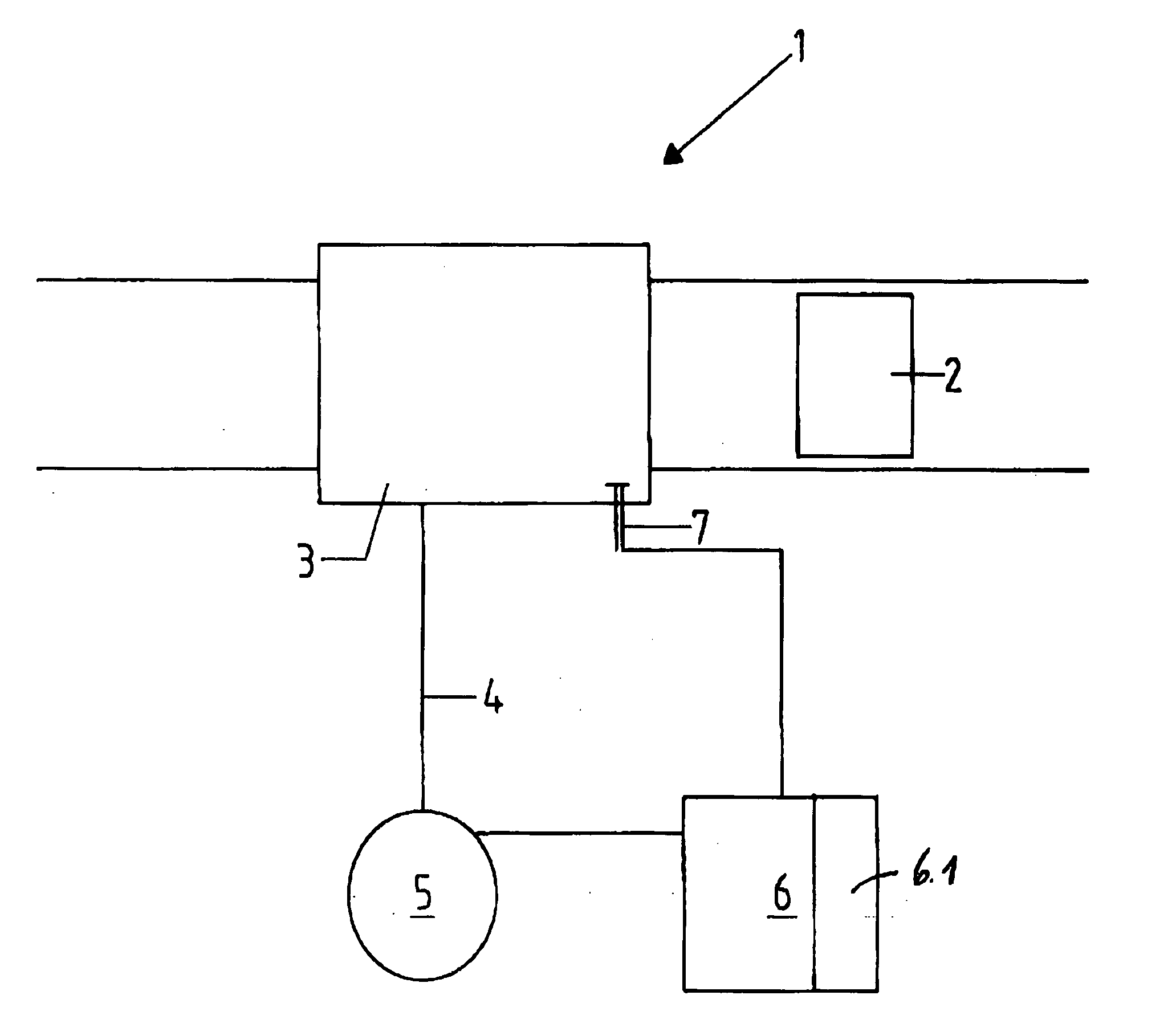
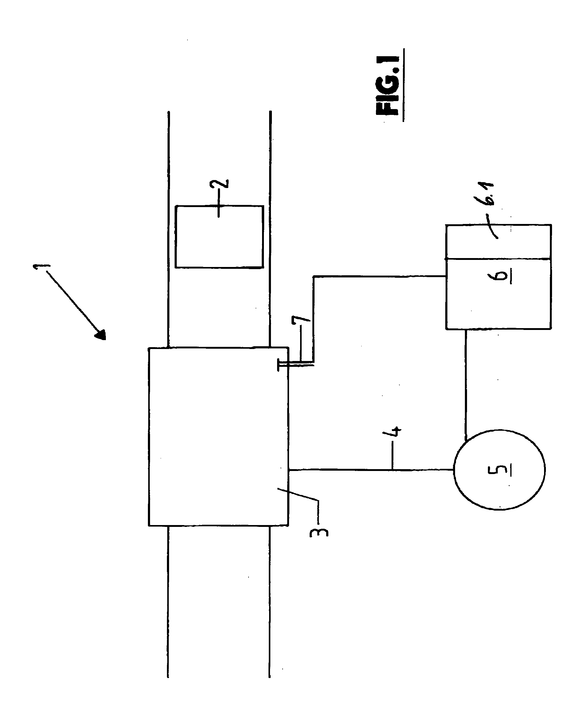
[0012] The vacuum packaging machine 1 depicted very schematically in FIG. 1 and used for packaging foods in vacuum-tight packages or containers 2, has a vacuum chamber 3 located in a packaging line, in which the containers 2 to be packaged are inserted and then sealed after evacuation. The vacuum chamber 3 is connected by means of a vacuum line 4 with a source for the vacuum, e.g. with a vacuum pump 5.

[0013] The evacuation time is controlled by means of an electronic analysis and control unit 6 and the signal of a pressure sensor 7, which in the depicted embodiment is provided at the vacuum chamber 3 and responds to the prevailing negative pressure in the vacuum chamber 3. Of course, the sensor 7 can also be located elsewhere, for example in the vacuum line 4 or in a separate measuring line connected with the interior of the chamber 3.

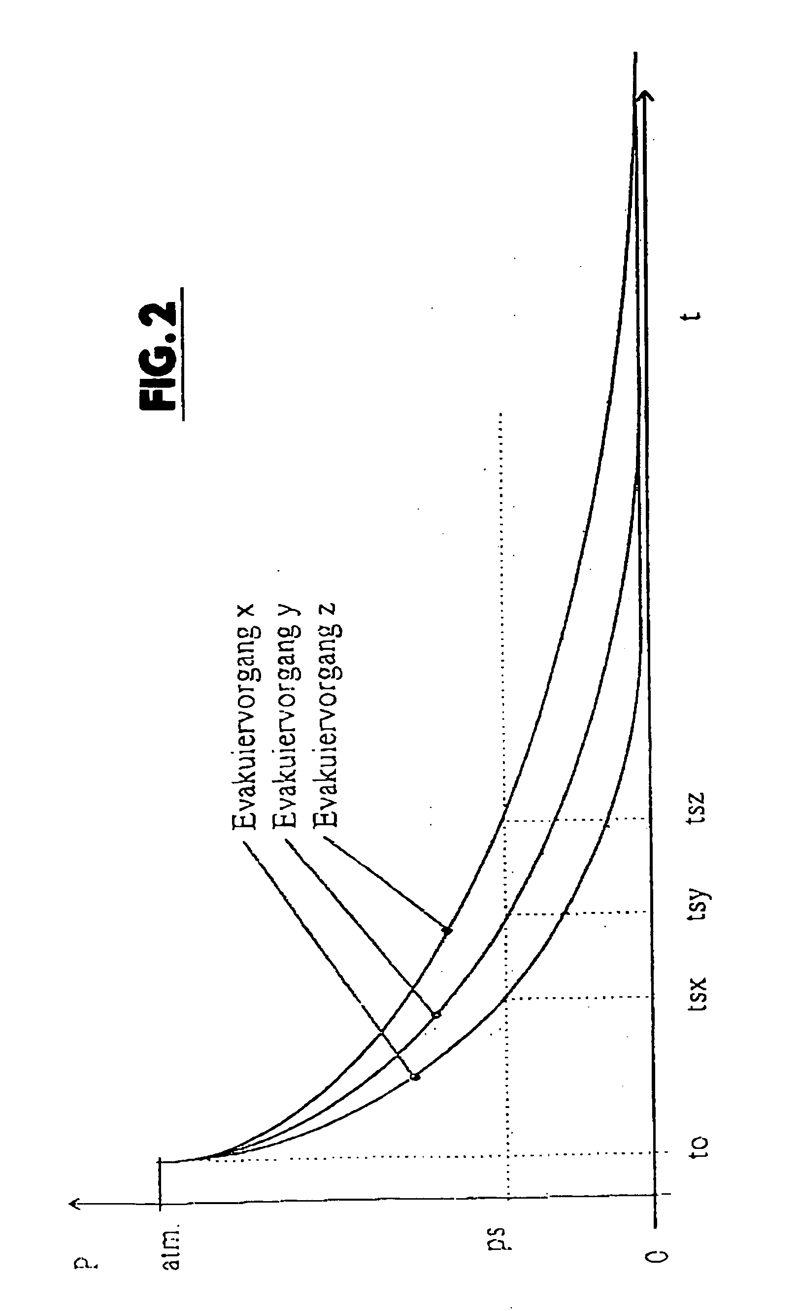
[0014] The sensor 7 is designed as a simple switch that responds to a negative pressure or a threshold pressure or a switching pressure ps and that ...


PUM


Abstract

In a method for controlling the evacuation process in a chamber to be evacuated in a vacuum packaging machine, the switching time starting with initiation of the evacuation process until reaching a specified threshold value or switching pressure (ps) is determined, then the evacuation time required for reaching a desired ultimate pressure is extrapolated from this switching time and the evacuation process is terminated upon reaching this evacuation time.

Description

BACKGROUND OF THE INVENTION [0001] The invention relates to a method for controlling a vacuum packaging machine and to a vacuum packaging machine. [0002] The following methods have been in use thus far for controlling the evacuation process in vacuum packaging machines: [0003] The simplest method used is time control, i.e. the evacuation process is positively ended after a specified time, which can be pre-selected at the machine, for example. The end result obtained by this method is very imprecise. The inaccuracy of this purely time-controlled process results from a number of parameters that affect the progression of the evacuation process, in particular also from the fact that the chamber volume changes depending on the quantity of goods inserted for packaging, and due to insertion or removal of compensating plates, etc. In order to attain a specific vacuum with this method, it is necessary to set the evacuation time somewhat higher, however with the disadvantage of a significant ...

Claims


Application Information

Patent Timeline
IPC IPC(8): B65B31/02
CPCB65B31/02
Inventor OESTERLEIN, ANDREAS
Owner OESTERLEIN ANDREAS
Why Eureka
Try Eureka