Motor torque control apparatus and method for automotive vehicle

Inactive Publication Date: 2006-01-26
NISSAN MOTOR CO LTD
View PDF16 Cites 95 Cited by
  • Summary
  • Abstract
  • Description
  • Claims
  • Application Information

AI Technical Summary

Benefits of technology

[0006] It is, therefore, an object of the present invention to provide motor torque control apparatus or method for an automotive vehicle, which is capable of attaining a desired

Problems solved by technology

Due to this, there is a possibility that the target driving force deviates from an actual dr

Method used


Image

  • Motor torque control apparatus and method for automotive vehicle
  • Motor torque control apparatus and method for automotive vehicle
  • Motor torque control apparatus and method for automotive vehicle

Examples


Example

[0051] A first embodiment of the motor torque control apparatus according to the present invention will now be explained with reference to FIG. 5.

[0052] In the motor torque control apparatus of the first embodiment, a disturbance observer estimates the driving force and then the estimated driving force is brought closer to a target value by way of servo control. The motor torque control apparatus of this embodiment (or, a controller composed of the disturbance observer and a motor torque control section of this embodiment) includes accelerator opening sensor 7, vehicle speed sensor 8 (corresponding to an output-shaft rotation speed sensing section (or, means)), a disturbance estimating section (or, means) 61, a driving force control section (or, means) 62, a disturbance cancellation quantity calculating section (or, means) 63, and a target motor torque calculating section (or, means) 64.

[0053] Vehicle speed sensor 8 senses an output-shaft (or, output-axis) rotation speed of hybrid...

Example

[0091] A second embodiment of the motor torque control apparatus according to the present invention will now be explained with reference to FIG. 8.

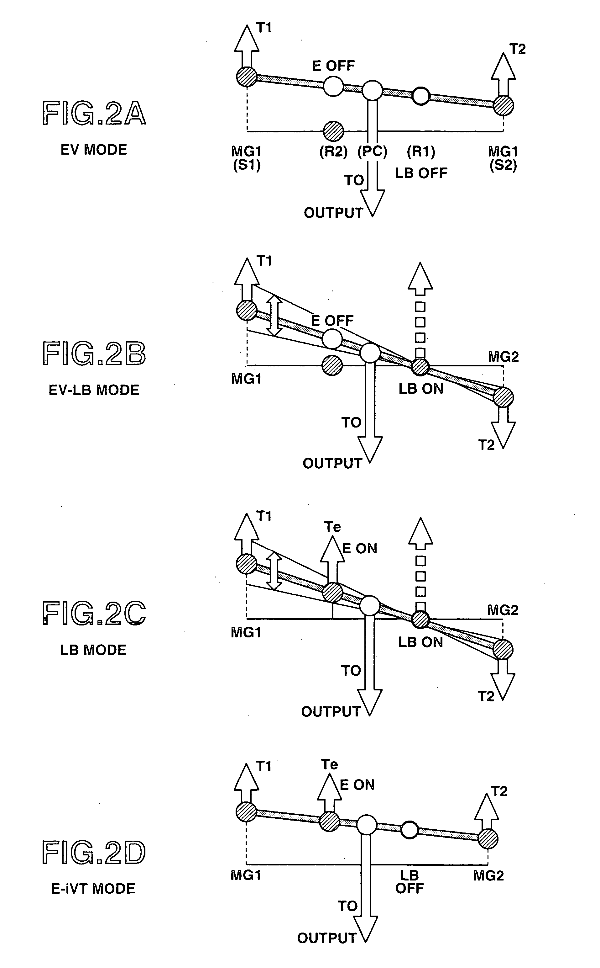
[0092] The second embodiment is an example which performs the speed ratio control and the driving force control (motor torque control), in the case of “EV mode” or “E-iVT mode” where low brake LB is open.

[0093] Namely, in the motor torque control apparatus of the second embodiment, the disturbance observer estimates the driving force, and then the driving force control torque is so calculated as to eliminate the difference between the estimated driving force and a target value (target driving force). Moreover, a shift (or, speed ratio) control torque is so calculated as to reduce the difference between an actual speed ratio and a target speed ratio. The motor torque is controlled or adjusted, in such a manner that this driving force control torque is only used for variation in acceleration / deceleration of the output shaft's rotation, an...

Example

[0117] A third embodiment of the motor torque control apparatus according to the present invention will now be explained with reference to FIG. 9.

[0118] In the motor torque control apparatus of the third embodiment, a disturbance observer estimates the running resistance torque (i.e., torque according to the running resistance) and the torsional torque of the drive shaft (wheel shaft), and then the target driving force is achieved by the disturbance observer. The motor torque control apparatus of this embodiment (or, the controller of the motor torque control apparatus in this embodiment) includes accelerator opening sensor 7, vehicle speed sensor 8 (corresponding to the output-shaft rotation speed sensing section (or, means)), a wheel speed sensor 13 (corresponding to a wheel rotation speed sensing section (or, means)), a disturbance estimating section (or, means) 161, a target acceleration calculating section (or, means) 162, a disturbance cancellation quantity calculating sectio...


PUM


Abstract

A motor torque control apparatus for an automotive vehicle includes a transmission which has either one of a fixed speed ratio and a variable speed ratio; at least one motor/generator coupled with the transmission as a propelling power source of the vehicle, a power of the power source being transmitted to a road wheel for propulsion of the vehicle through the transmission; and a controller configured to be electrically connected to the motor/generator for motor torque control. Moreover, this controller includes a disturbance observer that estimates a driving force, and a motor torque control section that controls the driving force estimated by the disturbance observer, to bring the estimated driving force closer to a target driving force by way of servo control.

Description

BACKGROUND OF THE INVENTION [0001] a) Field of the Invention [0002] The present invention relates to motor torque control apparatus and method for an electric or hybrid vehicle which has at least one motor / generator as a power source (or, drive source). [0003] b) Description of the Related Art [0004] A Japanese Patent Provisional Publication No. H8(1996)-232817 published on Sep. 10, 1996 exemplifies a previously proposed motor torque control apparatus for a hybrid vehicle which runs by torque produced by a motor in accordance with a target driving force. In this proposed motor torque control apparatus, a target motor torque is calculated according to a vehicle speed and an accelerator opening, and then the motor is so controlled as to achieve this target motor torque. SUMMARY OF THE INVENTION [0005] However, in the above-described previously proposed motor torque control technique, the target motor torque corresponding to the target driving force is calculated according to a vehicle...

Claims


Application Information

Patent Timeline
IPC IPC(8): H02P7/00B60K6/445
CPCB60K6/445B60L2240/423B60L2240/486B60W10/08B60W20/00B60W20/102Y02T10/6239B60W2710/083B60W2710/105B60W2720/106F16H2037/103Y02T10/642B60W30/20B60W20/11Y02T10/62Y02T10/64B60W10/10
Inventor JOE, SHINICHIROKAWABE, TAKETOSHI
Owner NISSAN MOTOR CO LTD
Why Eureka
Try Eureka