
Multimode detection

a detection method and multi-mode technology, applied in the field of communication systems, can solve problems such as intersymbol interference and multi-user interference, reduce computational complexity, and reduce the computational complexity of the system with multiple transmit antennas

Inactive Publication Date: 2006-01-26
TEXAS INSTR INC
View PDF10 Cites 42 Cited by
  • Summary
  • Abstract
  • Description
  • Claims
  • Application Information

AI Technical Summary

Benefits of technology

The present invention provides detectors and detection methods that can adapt to different conditions. These methods can be used in multiple-input multiple-output (MIMO) systems. The advantages of these methods include approaching maximum likelihood detection with less complexity than iterative interference cancellation detection.

Problems solved by technology

This leads to intersymbol interference and multi-user interference, and requires interference-resistant detectors and detection methods for interference-limited systems.
Interference-limited systems include multi-antenna systems with multi-stream or space-time coding which have spatial interference, multi-tone systems, TDMA systems having frequency selective channels with long impulse responses leading to intersymbol interference, CDMA systems with multi-user interference arising from loss of orthogonality of spreading codes, high data rate CDMA which in addition to multi-user interference also has intersymbol interference.
However, maximum likelihood sequence estimation has problems including impractically large computation complexity for systems with multiple transmit antennas because the decoding requires a search over the topological product of multiple copies of the symbol constellation.
Linear filtering detection, such as linear zero-forcing (ZF) and linear minimum squared error (MMSE), has lower computational complexity (search over a single symbol constellation) but has relatively poor performance due to excessive noise enhancement.
Such methods have moderate computational complexity but only moderate performance.
However, these methods have problems including trade-offs of performance and complexity which are inappropriate for many conditions.

Method used


Image

  • Multimode detection
  • Multimode detection
  • Multimode detection

Examples


Embodiment Construction

1. Overview

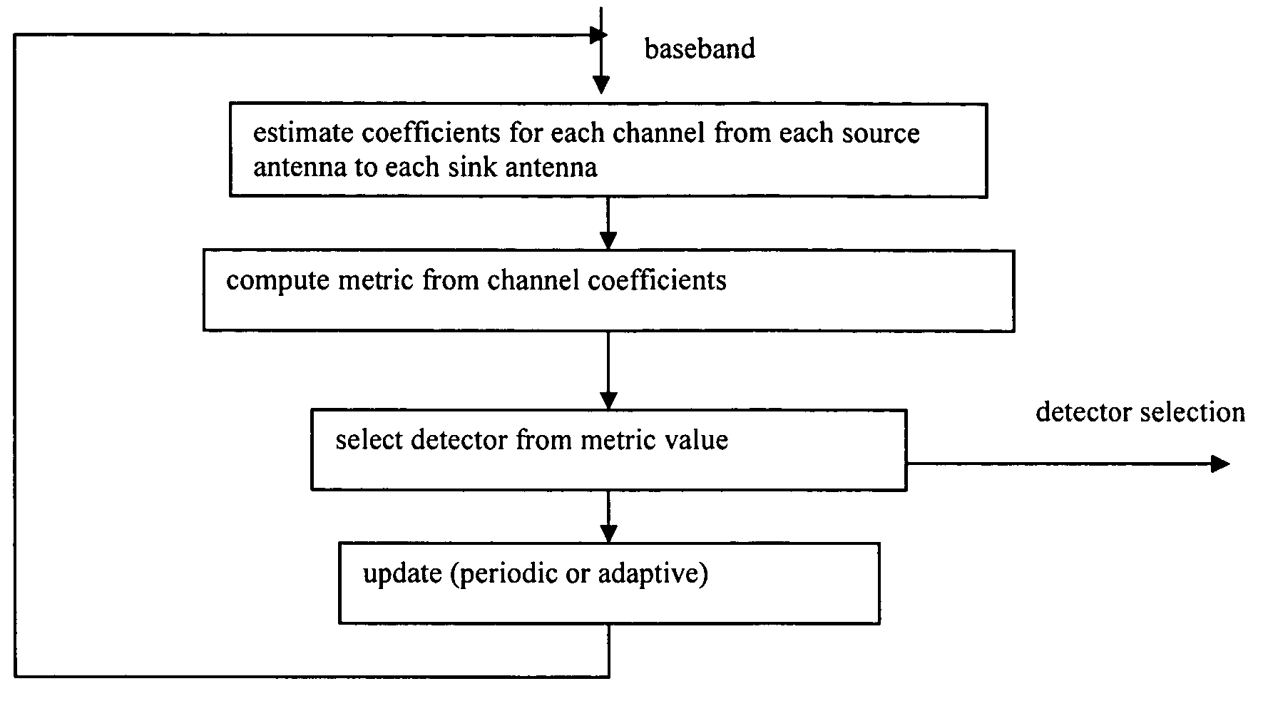
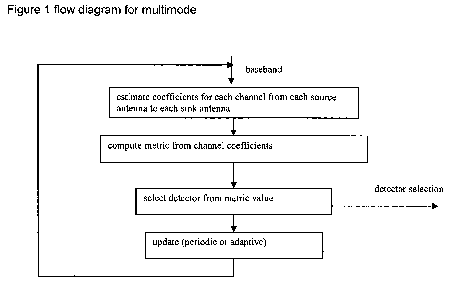
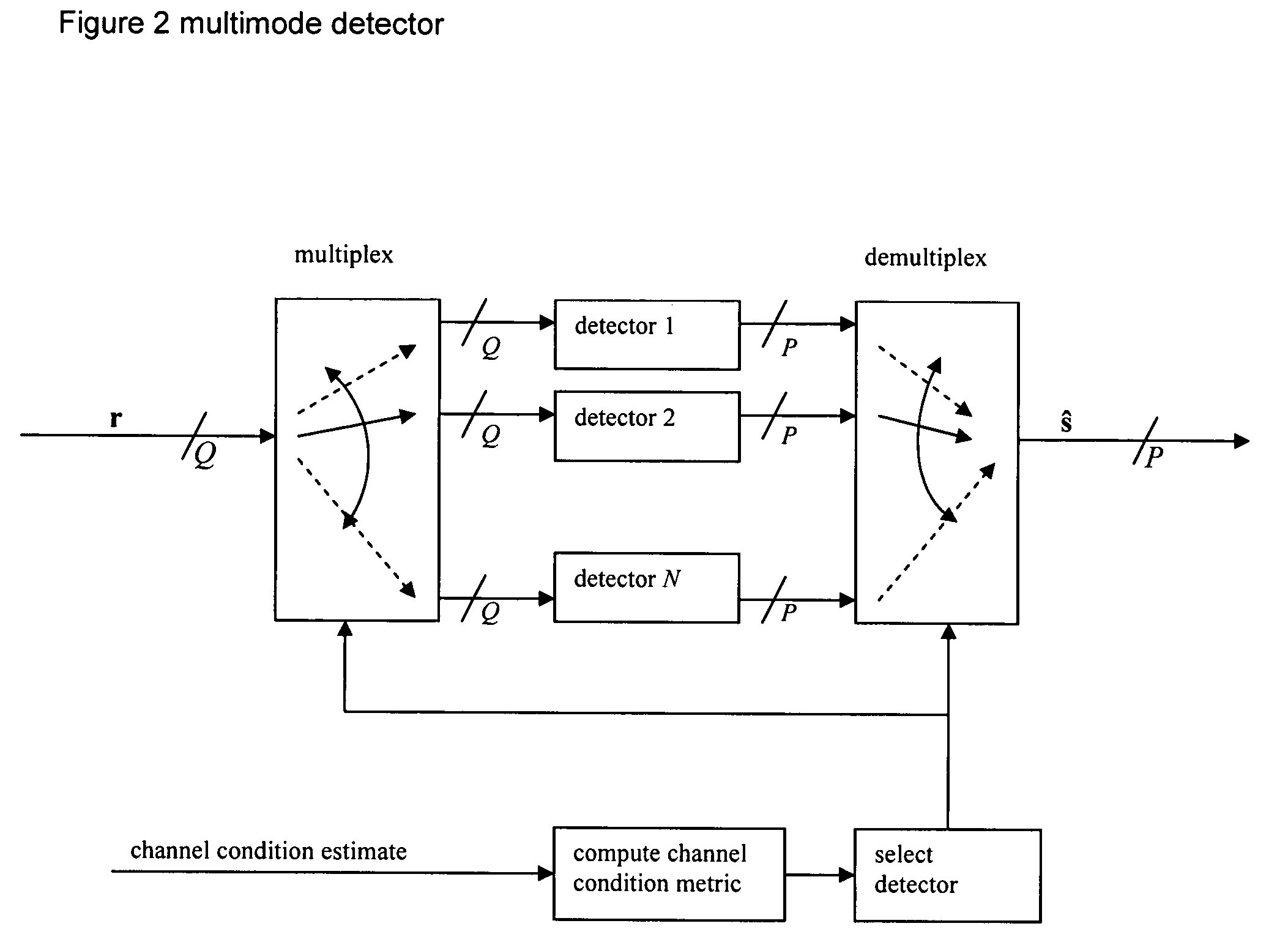
[0012] Preferred embodiment multimode detectors and detection methods have detection mode selection dependent upon channel estimation; FIG. 2 shows a preferred embodiment detector and FIG. 1 is a flow diagram of the mode selection operation which includes updating. The mode selection allows for high performance with lower effective computational complexity; indeed, a target performance (such as within 0.2 dB of maximum likelihood detection performance) could be specified and the lowest complexity (or lowest power consumption) detection meeting the performance target would be selected. Preferred embodiment receivers and transceivers include preferred embodiment detectors and / or detection methods, and apply to multi-input, multi-output (MIMO) antenna systems.

[0013] Preferred embodiment communication systems, such as cellular phones and wireless local area networks, include preferred embodiment receivers employing preferred embodiment detection. The detection computations...


PUM


Abstract

In a wireless MIMO system, a multimode detector selects detection mode by channel estimation: ill-conditioned channels trigger use of high performance detection, whereas well-behaved channels lead to low complexity detection. Detection modes typically include maximum likelihood, minimum mean squared error, zero forcing, and so forth.

Description

CROSS-REFERENCE TO RELATED APPLICATIONS [0001] The following copending application discloses related subject matter and have a common assignee with the present application: application Ser. No. 10 / 618,970, filed Jul. 14, 2003.BACKGROUND OF THE INVENTION [0002] The present invention relates to communication systems, and more particularly to multimode detectors and detection methods. [0003] Wireless communication systems typically use band-limited channels with time-varying (unknown) distortion and may have multi-users (such as multiple clients in a wireless LAN). This leads to intersymbol interference and multi-user interference, and requires interference-resistant detectors and detection methods for interference-limited systems. Interference-limited systems include multi-antenna systems with multi-stream or space-time coding which have spatial interference, multi-tone systems, TDMA systems having frequency selective channels with long impulse responses leading to intersymbol interfe...

Claims


Application Information

Patent Timeline
Patent Type & Authority Applications(United States)
IPC IPC(8): H03D1/00
CPCH04B7/0434H04L2025/03547H04L25/0204H04B7/0854
Inventor ONGGOSANUSI, EKO N.DABAK, ANAND G.HOSUR, SRINATH
Owner TEXAS INSTR INC
Learn More