Image processing method, image processing apparatus, and image processing program

Active Publication Date: 2006-01-26
PANASONIC CORP
View PDF7 Cites 77 Cited by
  • Summary
  • Abstract
  • Description
  • Claims
  • Application Information

AI Technical Summary

Benefits of technology

[0038] According to the present invention, a linearized image, which is an image in an ideal condition in which specular reflection is not caused, can be generated by a very simple constitution under general environment such as in a home.
[0039] In association th

Problems solved by technology

However, while the image processing as in the above Patent Document 1 is effective for image without noise, it cannot provide sufficient reliability and accuracy for images shot under general environment (for example, Non-patent Document 1).
As a result, the detection accuracy is lowered largely.
This lowers accuracy of stereo matching.
Moreover, this problem is caused not only by specular reflection but also by a shadow (cast shadow) cast by an object existing in the vicinity and a shadow (attached shadow) appearin

Method used


Image

  • Image processing method, image processing apparatus, and image processing program
  • Image processing method, image processing apparatus, and image processing program
  • Image processing method, image processing apparatus, and image processing program

Examples


embodiment 1

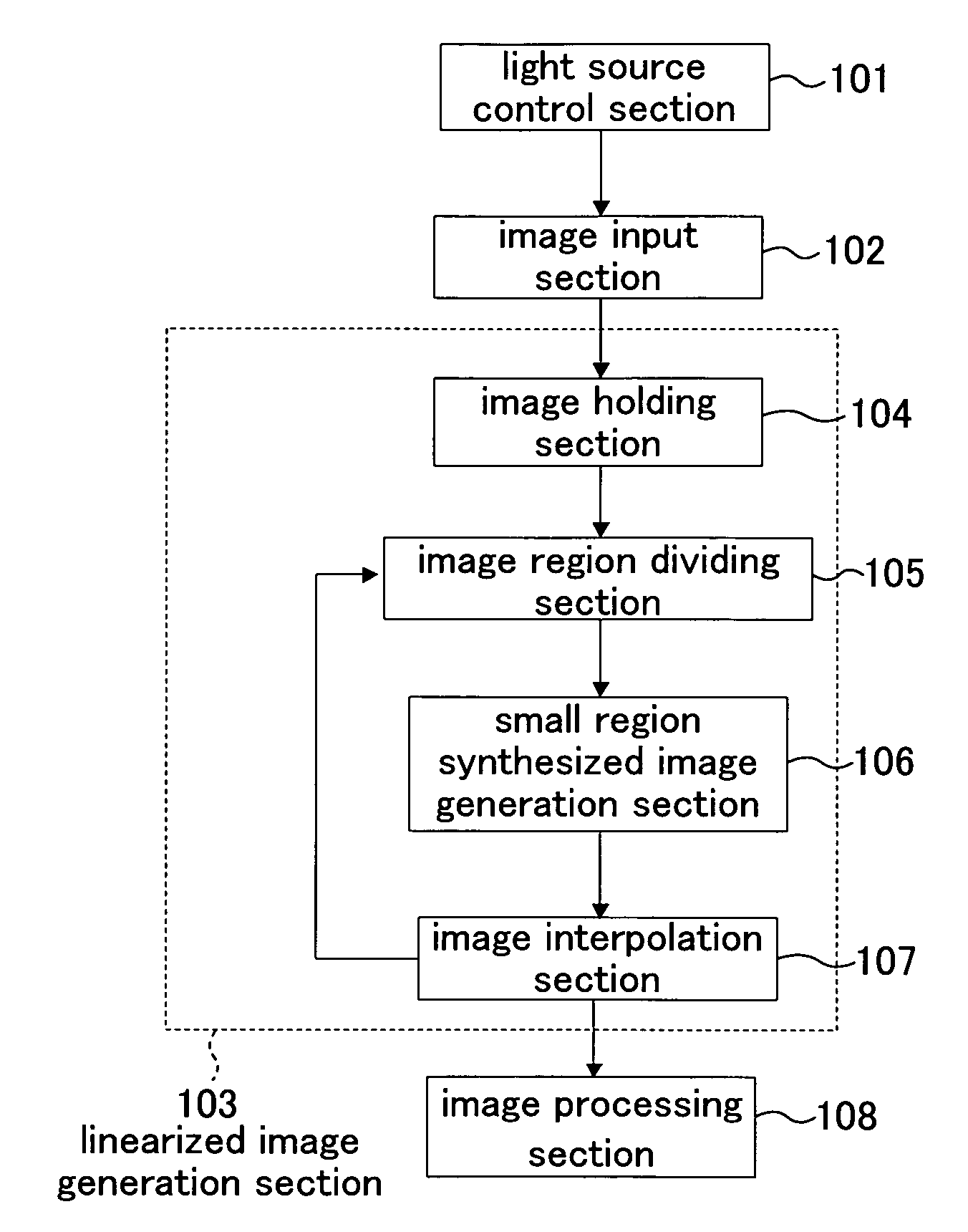
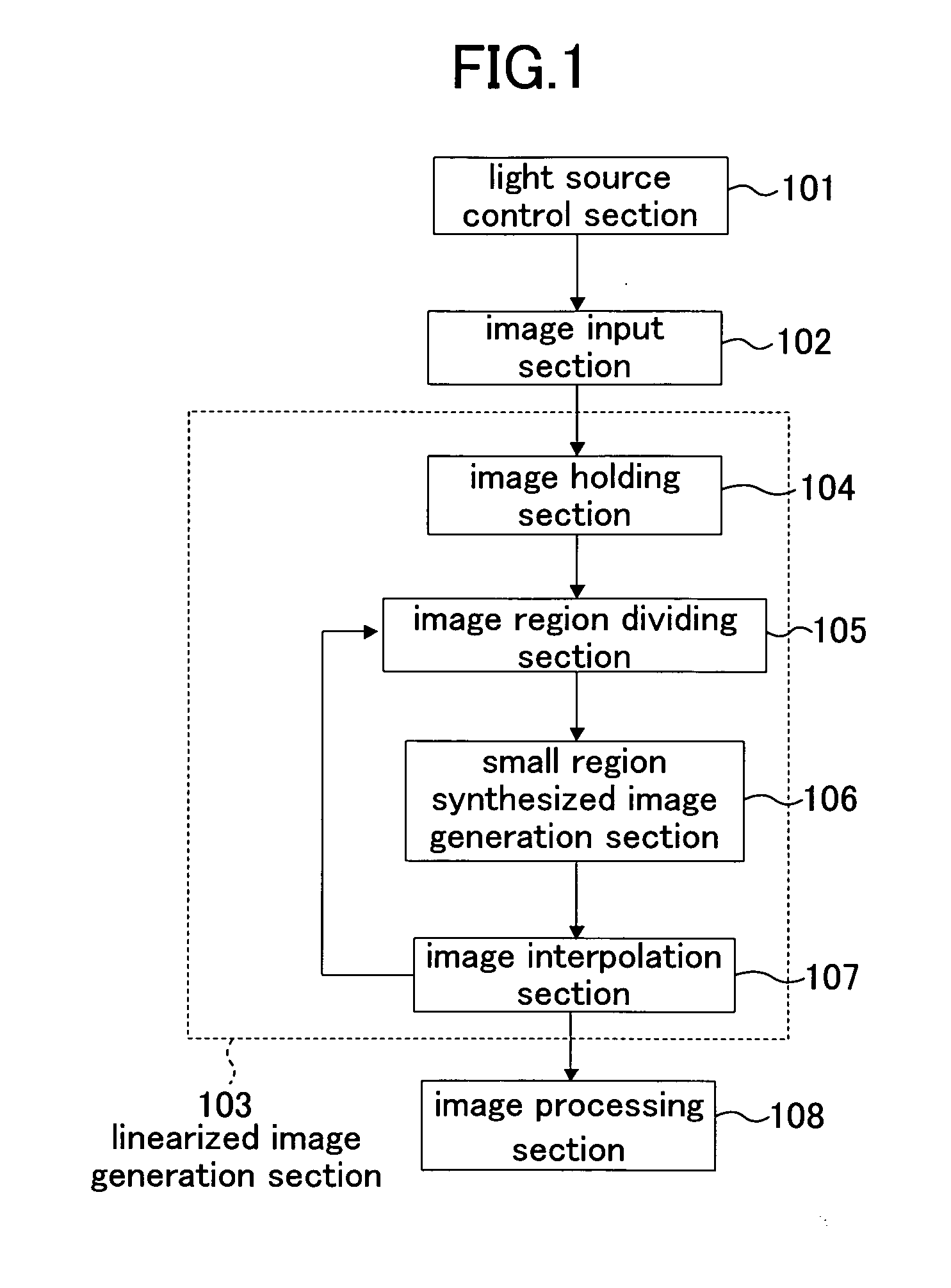
[0119]FIG. 1 is a block diagram showing a constitution of an image processing apparatus that executes an image processing method according to Embodiment 1 of the present invention. This image processing apparatus includes: a light source control section 101 that controls a position of a light source; an image input section 102 that inputs a plurality of images in a situation in which lighting condition is changed by the light source control section 101; and a linearized image generation section 103 that generates a linearized image using a plurality of images which are different from each other in lighting condition and are input through the image input section 102.

[0120] The linearized image generation section 103 includes: an image holding section 104 that holds a plurality of images input; an image region dividing section 105 that partitions an input image that the image holding section 104 holds into small regions; a small region synthesized image generation section 106 that ge...

modified examples

[0234] Further, the image interpolation section 107 may include control means for exchanging the following three pieces of processing. [0235] Interpolation processing is performed by the above method. [0236] An image generated by the small region synthesized image generation section 105 is sent to the image processing section 108 directly without performing the interpolation [0237] The small regions are changed in size and / or position by the image region dividing section 105 and a synthesized image is regenerated by the small region synthesized image generation section 106.

[0238] In the present embodiment, the processing is performed to each divided small region, and therefore, all the normal directions of selected three points are liable to be the same in the random sampling in RANSAC. In this case, the matrix D is degenerated, so that neither solution nor linearization coefficient can be obtained.

[0239] In this connection, whether the normal directions of three points sampled in...

embodiment 2

[0291]FIG. 32 is a view showing a constitution of an image processing apparatus that executes an image processing method according to Embodiment 2 of the present invention. In FIG. 32, the same constitutional elements as in FIG. 1 are assigned to the same reference numerals and description thereof is omitted.

[0292] In comparison of the constitution in FIG. 32 with that in FIG. 1, a lighting condition variation detection section 109 for detecting variation in lighting condition under shooting environment is provided instead of the light source control section 101. In the present embodiment, the image input section 102 performs shooting when variation in lighting condition is detected by the lighting condition variation detection section 109 to obtain a plurality of images. In other words, in the present embodiment, a plurality of images of which lighting condition is different from each other are obtained by performing shooting at variation in lighting condition, rather than the lig...


PUM


Abstract

An image region dividing section (105) partitions each of input images into a small regions, and a small region synthesized image generation section (106) generates a base image of each small region, which is an image including only diffuse reflection, from each input image. An image interpolation section (107) generates by interpolation a base image of a small region of which base image cannot be generated. A linearized image generation section (103) generates a linearized image, which is an image in an ideal state under given lighting condition, using the base image of each small region.

Description

CROSS REFERENCE TO RELATED APPLICATIONS [0001] This is a continuation of Application PCT / JP2005 / 003435 filed on Mach 2, 2005.BACKGROUND OF THE INVENTION [0002] 1. Field of the Invention [0003] The present invention relates to a image processing technology and particularly relates to a technology for removing influence of specular reflection and shadows which is a problem in processing images shot under general environment. [0004] 2. Description of the Prior Art [0005] Conventionally, methods using cameras are widely used for detecting position and posture of an object, recognizing an object, detecting motion of an object, and the like. These are realized by applying image processing, such as pattern matching, optical flow detection, and feature point extraction, to images shot by a camera. [0006] For example, for detecting position and posture of an object from images shot by a camera, there has been proposed a method in which a 3D model of the object is aligned to an image of a ste...

Claims


Application Information

Patent Timeline
IPC IPC(8): G06K9/34G06V10/20
CPCG06K9/36G06T2207/20021G06T5/50G06T5/20G06T5/008G06V10/20
Inventor SATONOBORI, KUNIOTAKATA, KAZUTOYO
Owner PANASONIC CORP
Why Eureka
Try Eureka