Electronic endoscope system for fluorescence observation

a fluorescence observation and endoscope technology, applied in the field of electronic endoscope systems, can solve the problems of observer fatigue, dramatic low brightness of fluorescence images, etc., and achieve the effect of reducing observer fatigu

Inactive Publication Date: 2006-01-26
HOYA CORP
View PDF5 Cites 57 Cited by
  • Summary
  • Abstract
  • Description
  • Claims
  • Application Information

AI Technical Summary

Benefits of technology

[0005] The present invention is advantageous in that an electronic endoscope system is provided that is capable of reducing observer's fatigue caused by great amount brightness difference when a normal image and a fluorescence image are displayed simultaneously.
[0006] According to an aspect of the invention, there is provided an electronic endoscope system used for observing living tissues inside a body cavity, provided with an image capturing system capable of capturing at least a normal image and a fluorescence image of the living tissues, an illuminating device having a white light source emitting white light and an excitation light source that emits excitation light having a predetermined wavelength, the living tissues emitting autofluorescence when irradiated with the excitation light, at least one display device configured to display the normal image and the fluorescence image, and a brightness control system configured to adjust brightness of at least one of the normal image and the fluorescence image to reduce brightness difference between the normal image and the fluorescence image to be displayed.
[0007] Optionally, the brightness control system may include brightness detectors configured to detect the brightness of the normal image and the fluorescence image and a brightness comparing system configured to compare the brightness between the normal image and the fluorescence image that are displayed simultaneously, the brightness control system controlling the brightness of at least one of the normal image and the fluorescence image that is detected by one of the brightness detectors to reduce the brightness difference between the normal image and the fluorescence image based on a comparison result analyzed by the brightness comparing system.
[0019] Optionally, the image capturing system may include an objective lens that receives light from the living tissues and forms an image thereof, an imaging device that receives the formed image and outputs an image signal corresponding to the received image, and an excitation light cut filter configured to eliminate the wavelength components equivalent to the excitation light from light directed to the imaging device.

Problems solved by technology

However, when the normal image and the fluorescence image are concurrently displayed as moving images, the brightness of the fluorescence image is dramatically low in comparison with the normal image.
Therefore, when both kinds of images are displayed side by side on the monitor as the images are without modification, the great amount brightness difference causes a problem that an observer gets needlessly tired.

Method used


Image

  • Electronic endoscope system for fluorescence observation
  • Electronic endoscope system for fluorescence observation
  • Electronic endoscope system for fluorescence observation

Examples


Embodiment Construction

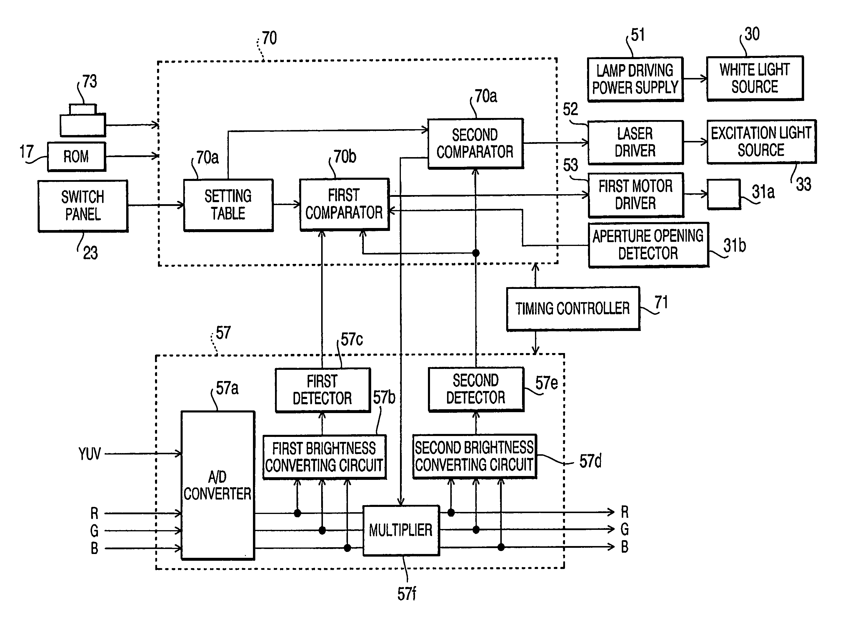
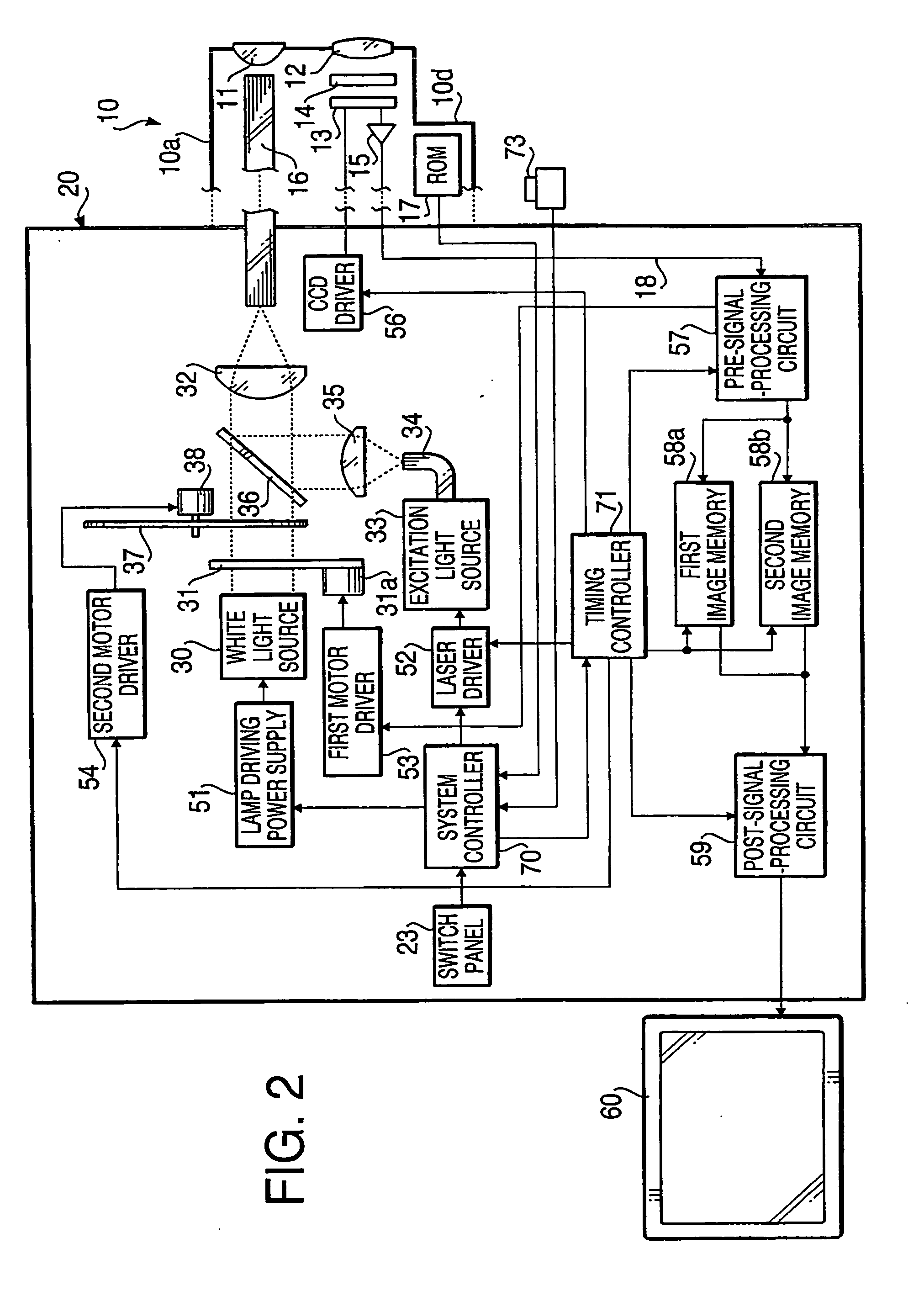
[0033] Hereinafter, an electronic endoscope system according to two embodiments of the present invention will be described with reference to the accompanying drawings. The electronic endoscope system of the embodiment is directed to a system that is adapted to observe a fluorescence image of autofluorescence emitted from a body cavity wall irradiated with excitation light on a display device such as a monitor, as well as a normal image of the body cavity wall illuminated with white light.

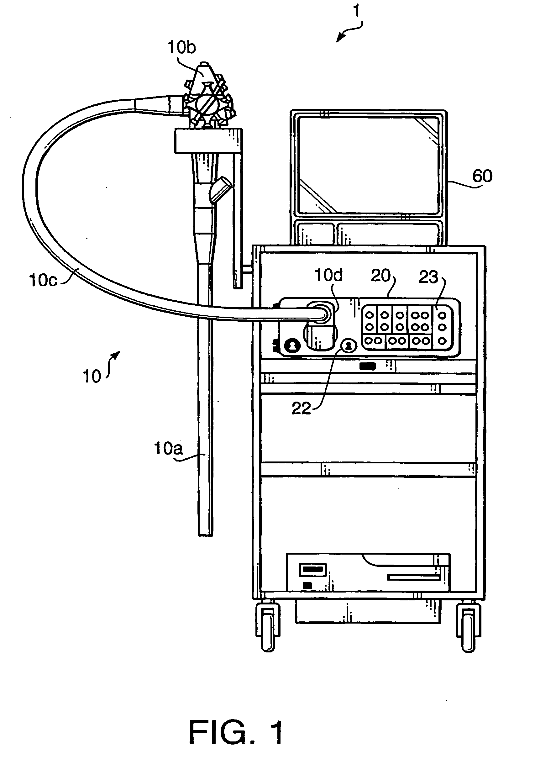
[0034]FIG. 1 schematically shows an external view of an electronic endoscope system 1 according to a first embodiment of the invention, and FIG. 2 shows a block diagram illustrating an internal constitution of the electronic endoscope system 1. As shown in FIG. 1, the electronic endoscope system is provided with a fluorescence observation endoscope 10, a light source apparatus 20, and a monitor 60.

[0035] The fluorescence observation endoscope 10, which is adapted to fluorescence observation by mod...


PUM


Abstract

An electronic endoscope system, which is adapted to observe a fluorescence image of autofluorescence emitted from a body cavity wall irradiated with excitation light as well as a normal image of the body cavity wall illuminated with white light on a display device, includes a brightness control system configured to adjust brightness of at least one of the normal image and the fluorescence image to reduce brightness difference between the normal image and the fluorescence image to be displayed.

Description

BACKGROUND OF THE INVENTION [0001] The present invention relates to an electronic endoscope system that is adapted to observe a fluorescence image of autofluorescence emitted from a body cavity wall irradiated with excitation light, as well as a normal image of the body cavity wall illuminated with white light, on a display device such as a monitor. [0002] An example of such an electronic endoscope system is disclosed in Japanese Patent Provisional Publications No. HEI 9-066023. The system disclosed in this publication includes a first solid-state imaging device that takes a fluorescence image, and a second solid-state imaging device that takes an RGB color image with illuminating light in accordance with a frame sequential method. In the system, signals outputted from the first and second solid-state imaging devices are processed by video circuits for fluorescence images and for normal images, respectively. The signals are then synthesized by an image synthetic circuit, and are dis...

Claims


Application Information

Patent Timeline
Patent Type & Authority Applications(United States)
IPC IPC(8): A61B1/06A61B6/00
CPCA61B1/00009A61B1/043A61B5/0071A61B1/0646A61B1/00039A61B1/00186A61B1/0638A61B5/0084A61B1/00042
Inventor SUGIMOTO, HIDEO
Owner HOYA CORP
Why Eureka
Try Eureka