Multiple computer architecture with synchronization

a multi-computer, synchronized technology, applied in the field of computers, can solve the problems of inability to scale over “commodity” (or mass produced) computers and networks, invariably increasing the administrative overhead of machines, and extremely expensive not only to manufacture but to administer single system image concepts

Active Publication Date: 2006-01-26
WARATEK LTD
View PDF71 Cites 93 Cited by
  • Summary
  • Abstract
  • Description
  • Claims
  • Application Information

AI Technical Summary

Problems solved by technology

The bus 4 suffers from a number of problems including so called bus “queues” formed by units wishing to gain an access to the bus, contention problems, and the like.
These problems can, to some extent, be alleviated by various stratagems including cache memory, however, such stratagems invariably increase the administrative overhead of the machine 1.
Although super computers have been technically successful in achieving high computational rates, they are not commercially successful in that their inherent complexity makes them extremely expensive not only to manufacture but to administer.
In particular, the single system image concept has never been able to scale over “commodity” (or mass produced) computers and networks.
In particular, the Single System Image concept has only found practical application on very fast (and hence very expensive) computers interconnected by very fast (and similarly expensive) networks.
Firstly, it is a difficult job to partition the application and this must be done manually.
Secondly, communicating data, partial results, results and the like over the network 14 is an administrative overhead.
Thirdly, the need for partitioning makes it extremely difficult to scale upwardly by utilising more machines since the application having been partitioned into, say three, does not run well upon four machines.
Fourthly, in the event that one of the machines should become disabled, the overall performance of the entire system is substantially degraded.
This approach does operate, is scalable and mainly suffers from the disadvantage that it is difficult to administer the network.

Method used


Image

  • Multiple computer architecture with synchronization
  • Multiple computer architecture with synchronization
  • Multiple computer architecture with synchronization

Examples


Embodiment Construction

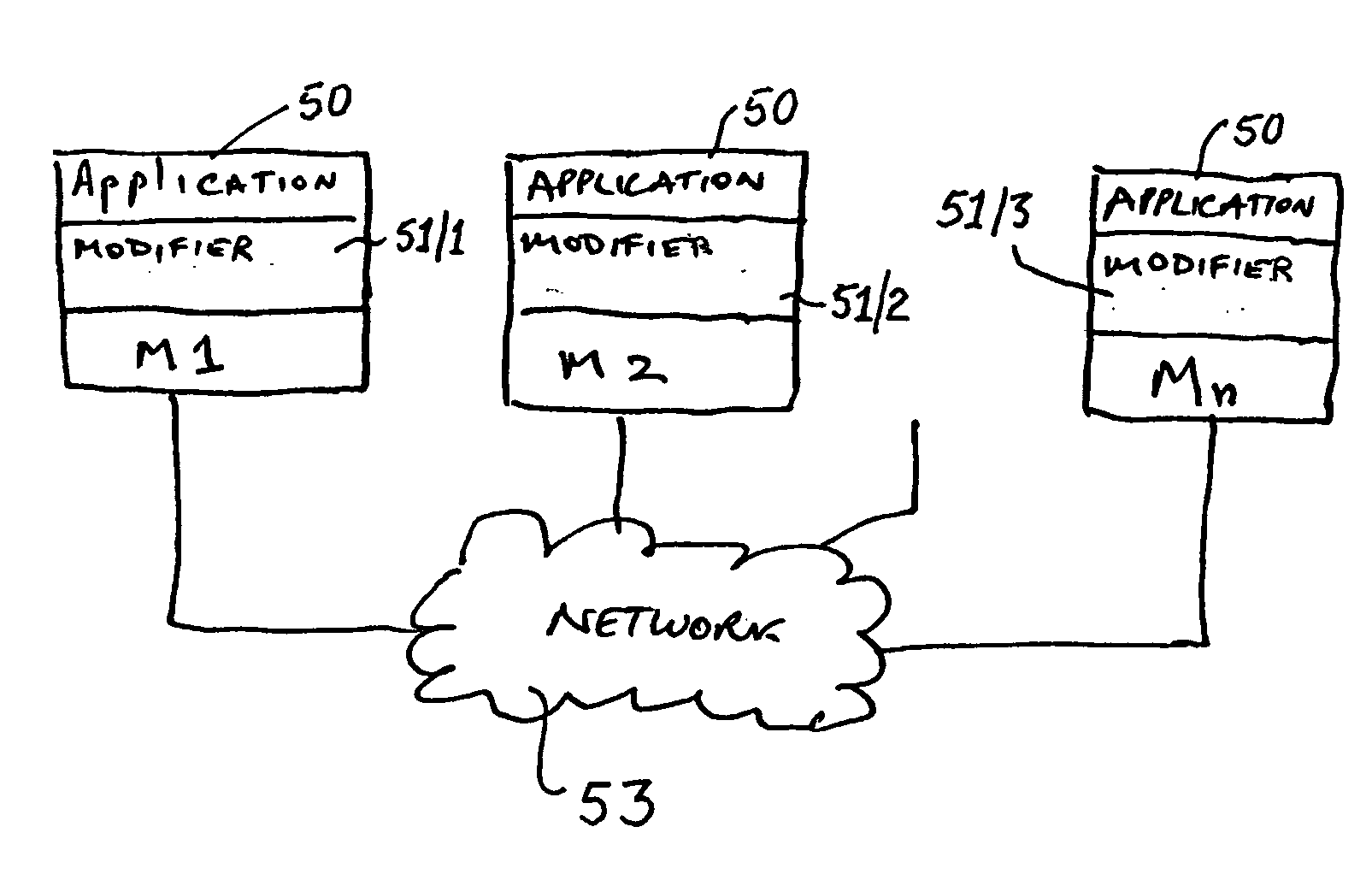
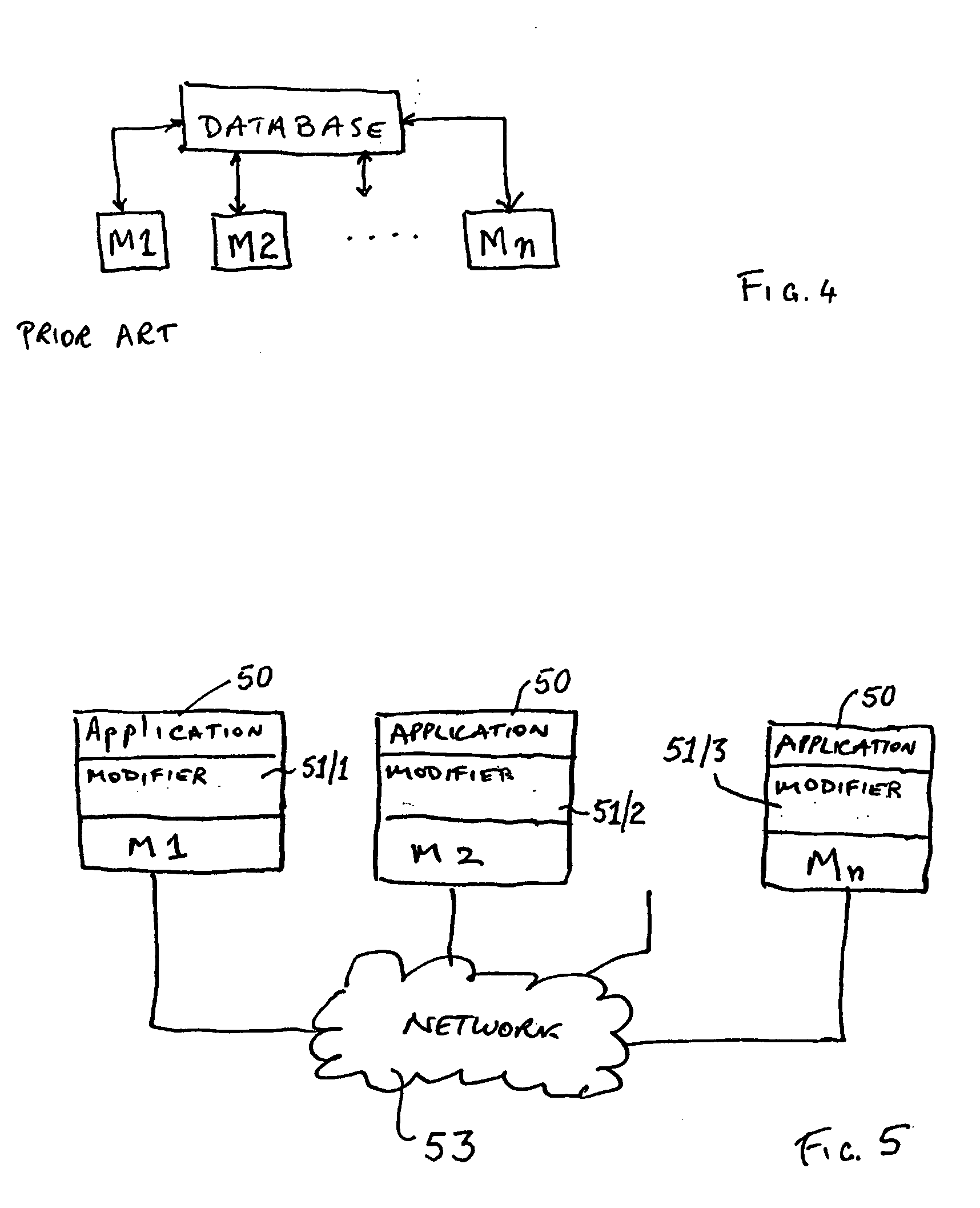
[0047] In connection with FIG. 5, in accordance with a preferred embodiment of the present invention a single application program 50 can be operated simultaneously on a number of machines M1, M2 . . . Mn communicating via network 53. As it will become apparent hereafter, each of the machines M1, M2 . . . Mn operates with the same application program 50 on each machine M1, M2 . . . Mn and thus all of the machines M1, M2 . . . Mn have the same application code and data 50. Similarly, each of the machines M1, M2 . . . Mn operates with the same (or substantially the same) modifier 51 on each machine M1, M2 . . . Mn and thus all of the machines M1, M2 . . . Mn have the same (or substantially the same) modifier 51 with the modifier of machine M2 being designated 51 / 2. In addition, during the loading of, or preceding the execution of, the application 50 on each machine M1, M2 . . . Mn, each application 50 has been modified by the corresponding modifier 51 according to the same rules (or su...


PUM


Abstract

The present invention discloses a modified computer architecture (50, 71, 72) which enables an applications program (50) to be run simultaneously on a plurality of computers (M1, . . . Mn). Shared memory at each computer is updated with amendments and / or overwrites so that all memory read requests are satisfied locally. During initial program loading (75), or similar, instructions which result in the application program (50) acquiring (or releasing) a lock on a particular asset (50A, 50X-50Y) (synchronization) are identified. Additional instructions are inserted (162, 163) to result in a modified synchronization routine with which all computers are updated.

Description

FIELD OF THE INVENTION [0001] The present invention relates to computers and, in particular, to a modified machine architecture which enables the operation of an application program simultaneously on a plurality of computers interconnected via a communications network. BACKGROUND ART [0002] Ever since the advent of computers, and computing, software for computers has been written to be operated upon a single machine. As indicated in FIG. 1, that single prior art machine 1 is made up from a central processing unit, or CPU, 2 which is connected to a memory 3 via a bus 4. Also connected to the bus 4 are various other functional units of the single machine 1 such as a screen 5, keyboard 6 and mouse 7. [0003] A fundamental limit to the performance of the machine 1 is that the data to be manipulated by the CPU 2, and the results of those manipulations, must be moved by the bus 4. The bus 4 suffers from a number of problems including so called bus “queues” formed by units wishing to gain a...

Claims


Application Information

Patent Timeline
Patent Type & Authority Applications(United States)
IPC IPC(8): G06F9/44G06F3/00G06F9/445G06F9/46G06F12/00
CPCG06F9/445G06F12/00G06F8/75G06F9/45504G06F9/52G06F9/46
Inventor HOLT, JOHN M.
Owner WARATEK LTD
Why Eureka
Try Eureka