Waterfall waterjet with debris removing outlet

Inactive Publication Date: 2006-02-02
CUSTOM MOLDED PROD
View PDF9 Cites 19 Cited by
  • Summary
  • Abstract
  • Description
  • Claims
  • Application Information

AI Technical Summary

Benefits of technology

[0008] Briefly described, the present invention is a waterfall waterjet that produces a waterfall into a spa, swimming pool, tub, reservoir, or the like, and that incorporates an alternate flowpath for the water through the device, or an alternate outlet, so that debris trapped inside the device can be flushed out. The device also provides a means for filling such a reservoir with water. For simplicity, spas, swimming pools, tubs or the like, and all such reservoirs and artificial bodies of water, together or separately will be referred to as spas or

Problems solved by technology

Further, the device will function even if there are no baffles, th

Method used


Image

  • Waterfall waterjet with debris removing outlet
  • Waterfall waterjet with debris removing outlet
  • Waterfall waterjet with debris removing outlet

Examples


Embodiment Construction

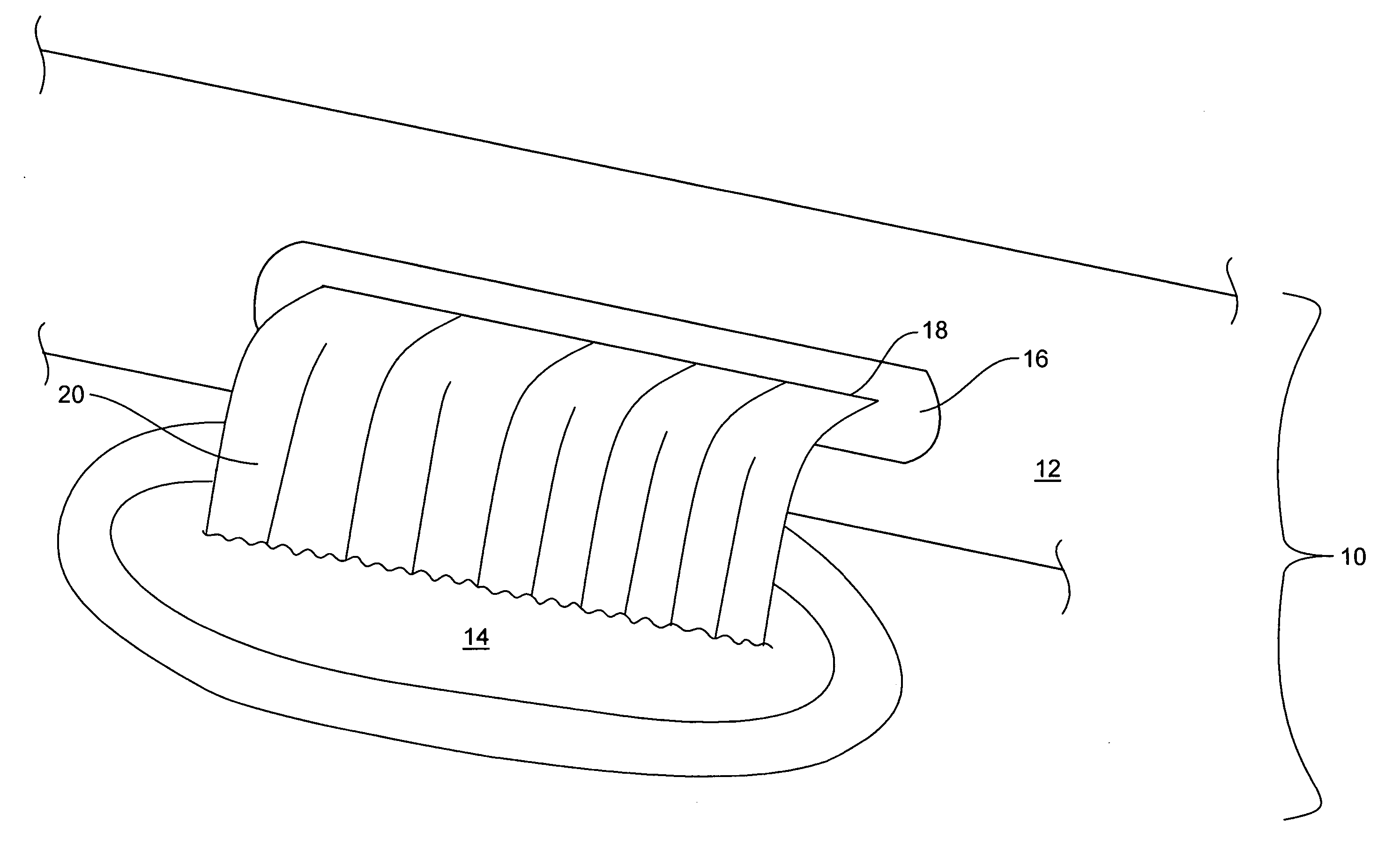
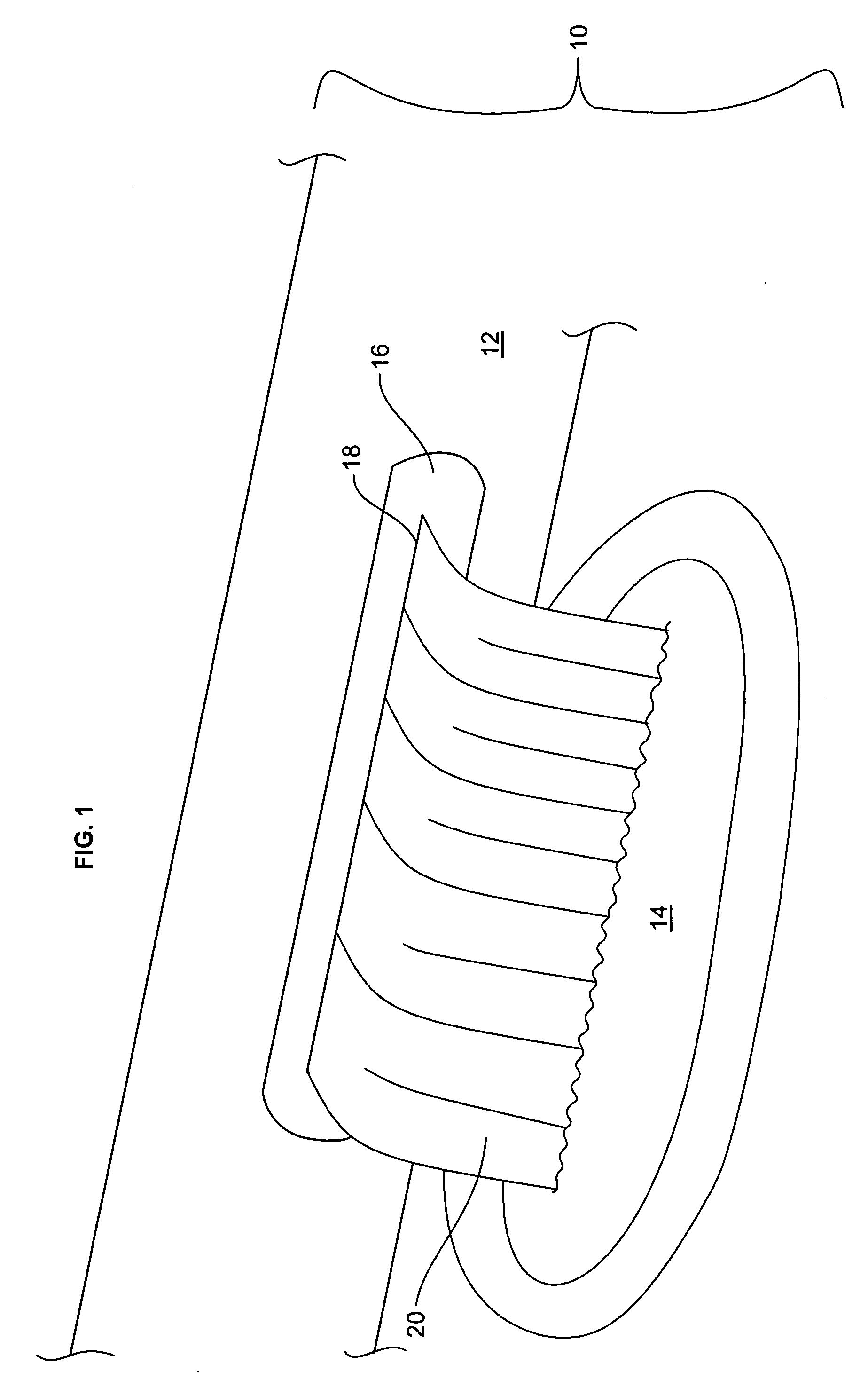
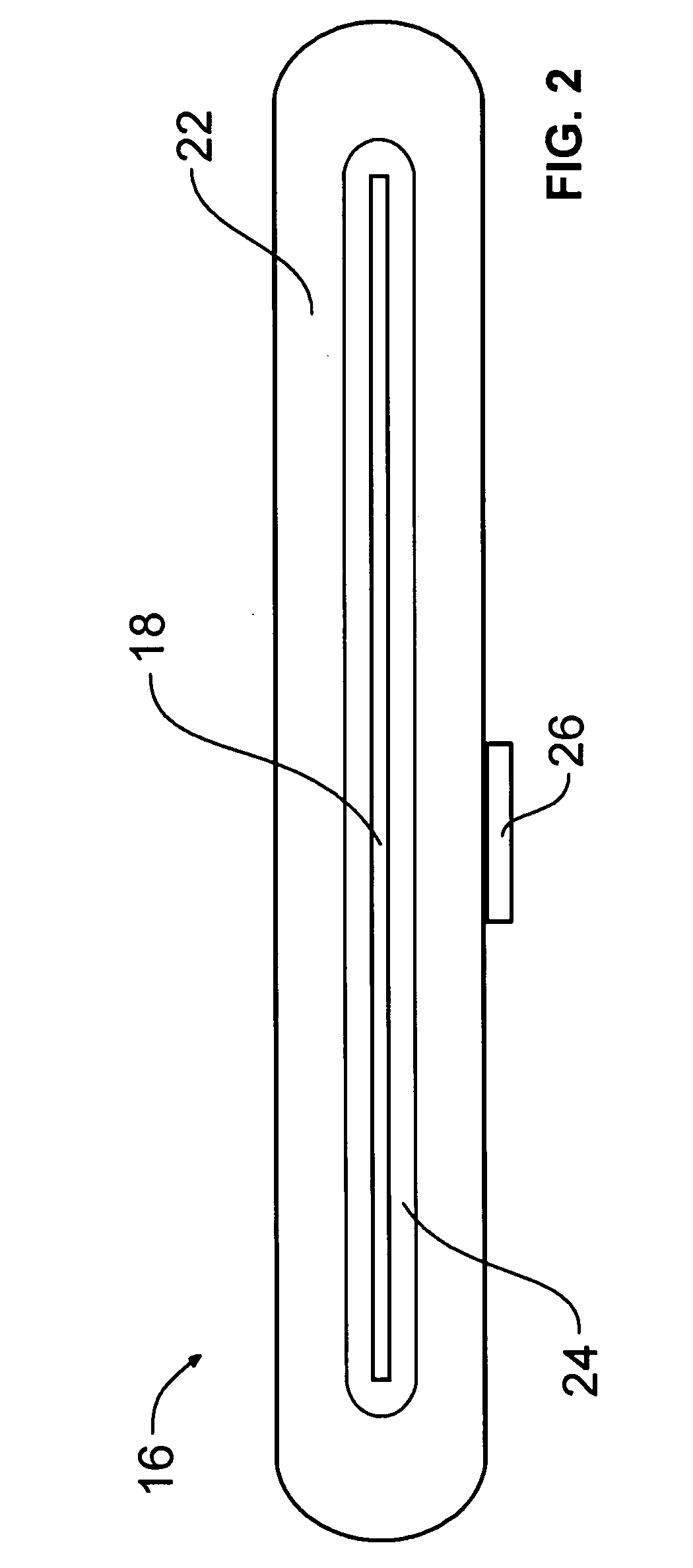
[0028] Illustrative embodiments of a waterfall waterjet 16 according to the present invention are shown in FIGS. 1 through 7. FIG. 1 is a perspective view of one embodiment of the present invention for producing a waterfall into the water of a spa. FIG. 2 is a front view of the embodiment shown in FIG. 1. FIG. 3A is a sectional top view of the invention with the debris outlets closed. FIG. 3B is a sectional top view of the invention with the debris outlets opened. FIG. 4 is an exploded view of illustrative components of the embodiment of the invention shown in FIG. 1. FIG. 5 is an exploded side view of the invention. FIG. 6 is a sectional side view of the invention showing the inflow of water into the invention. FIG. 7 is a bottom view of the invention showing the relative placement of a slide bar for opening and closing the debris outlets. FIG. 8 is a view of an alternate method of closing the debris outlets of the present invention showing a “water gun plug”. FIG. 9 illustrates an...


PUM


Abstract

A device for producing a waterfall comprising a waterfall waterjet with at least one chamber, at least one primary outlet, at least one debris outlet, a water source fluidly connected to the waterfall waterjet, a means of opening and closing the debris outlet, and a means of anchoring the waterfall waterjet to a spa.

Description

BACKGROUND OF THE INVENTION [0001] 1. Technical Field [0002] The present invention generally is in the field of devices for generating waterfalls, and more particularly is in the field of devices for generating aesthetically pleasing waterfalls in spas, swimming pools, tubs and the like. The present invention further relates to a more cost efficient design and installation system for waterfall devices in spas, swimming pools, tubs, and the like, that include an alternate flowpath for the water through the device, or an alternate outlet for water from the device, so that debris and sediment trapped inside the device may be removed from the device. [0003]2. Prior Art [0004] Few applications derive more benefit from the addition of waterfalls or fountains than artificial bodies of water such as spas, swimming pools, and tubs. The popularity of waterfalls and fountains in such structures is probably associated with the numerous aesthetic and practical applications that make waterfalls d...

Claims


Application Information

Patent Timeline
IPC IPC(8): E04H4/00
CPCE04H4/148E04H4/14
Inventor LI, H. CHARLESMOORE, ROBERT D.
Owner CUSTOM MOLDED PROD
Why Eureka
Try Eureka