Combined cycle power plant

a combined cycle and power plant technology, applied in the direction of machines/engines, turbine/propulsion fuel valves, lighting and heating apparatus, etc., can solve the problems of not being able to inert this part of the fuel system for maintenance, and the time required for starting up the gasifier of an igcc power plant can be a number of hours

Inactive Publication Date: 2011-12-22
SIEMENS AG
View PDF21 Cites 2 Cited by
  • Summary
  • Abstract
  • Description
  • Claims
  • Application Information

AI Technical Summary

Benefits of technology

In an advantageous manner the flushing medium is routed between a mixing facility connected into the gas line which is used for the admixture of nitrogen to the fuel and a syngas cleaning system, so that the fuel conditioning system can be flushed out independently of the fuel cleaning system. As described above this is of particular interest with poly-generation systems, in which gasifier and gas treatment can continue to be in operation while the fuel system and the downstream systems are taken out of operation.

Problems solved by technology

Without the described concept it would not be possible to inert this part of the fuel system for maintenance purposes or the like, since gasifier and gas treatment are still in operation.
Starting up the gasifier of an IGCC power plant can take a number of hours.

Method used


Image

  • Combined cycle power plant
  • Combined cycle power plant

Examples


Embodiment Construction

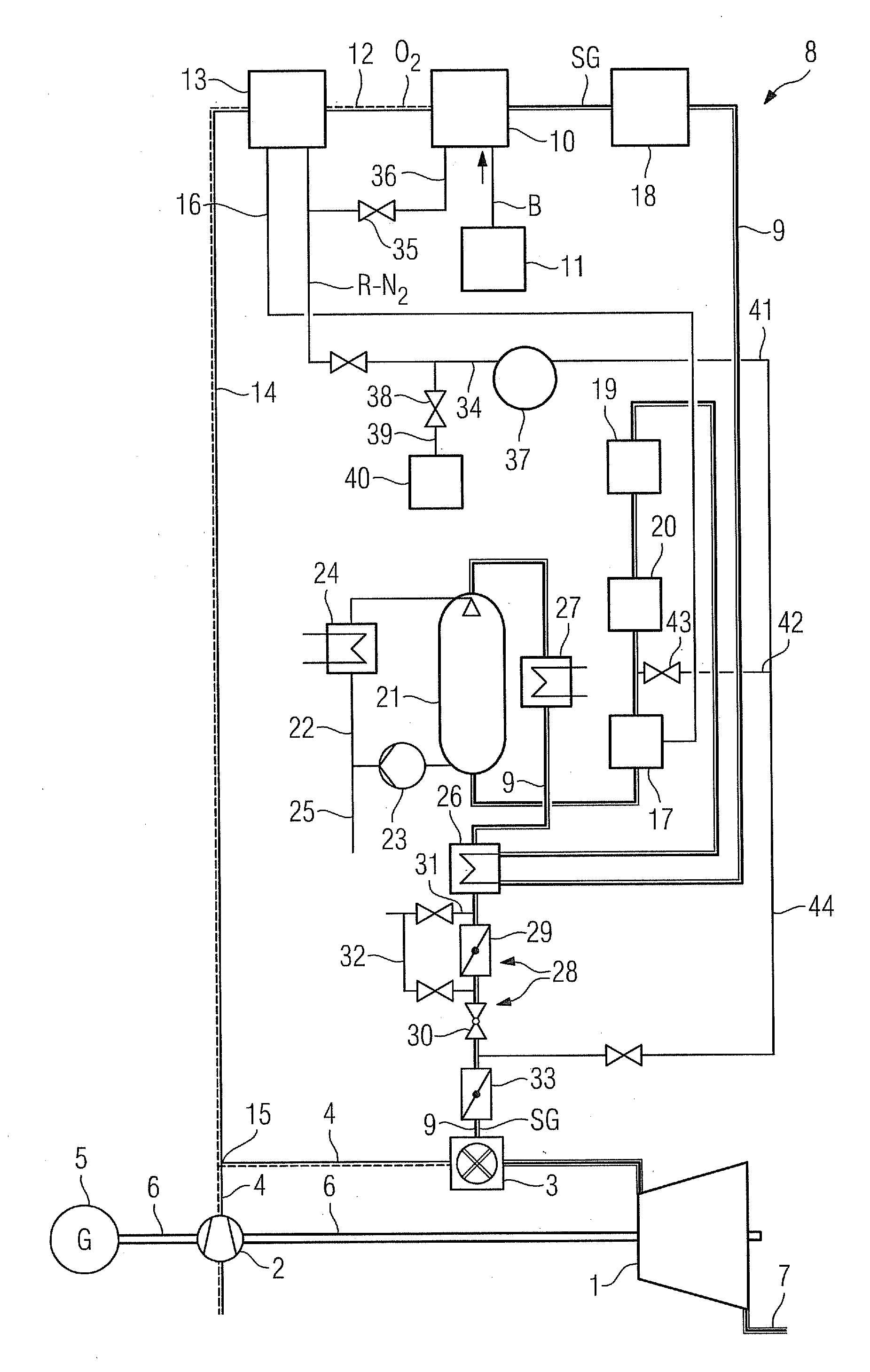
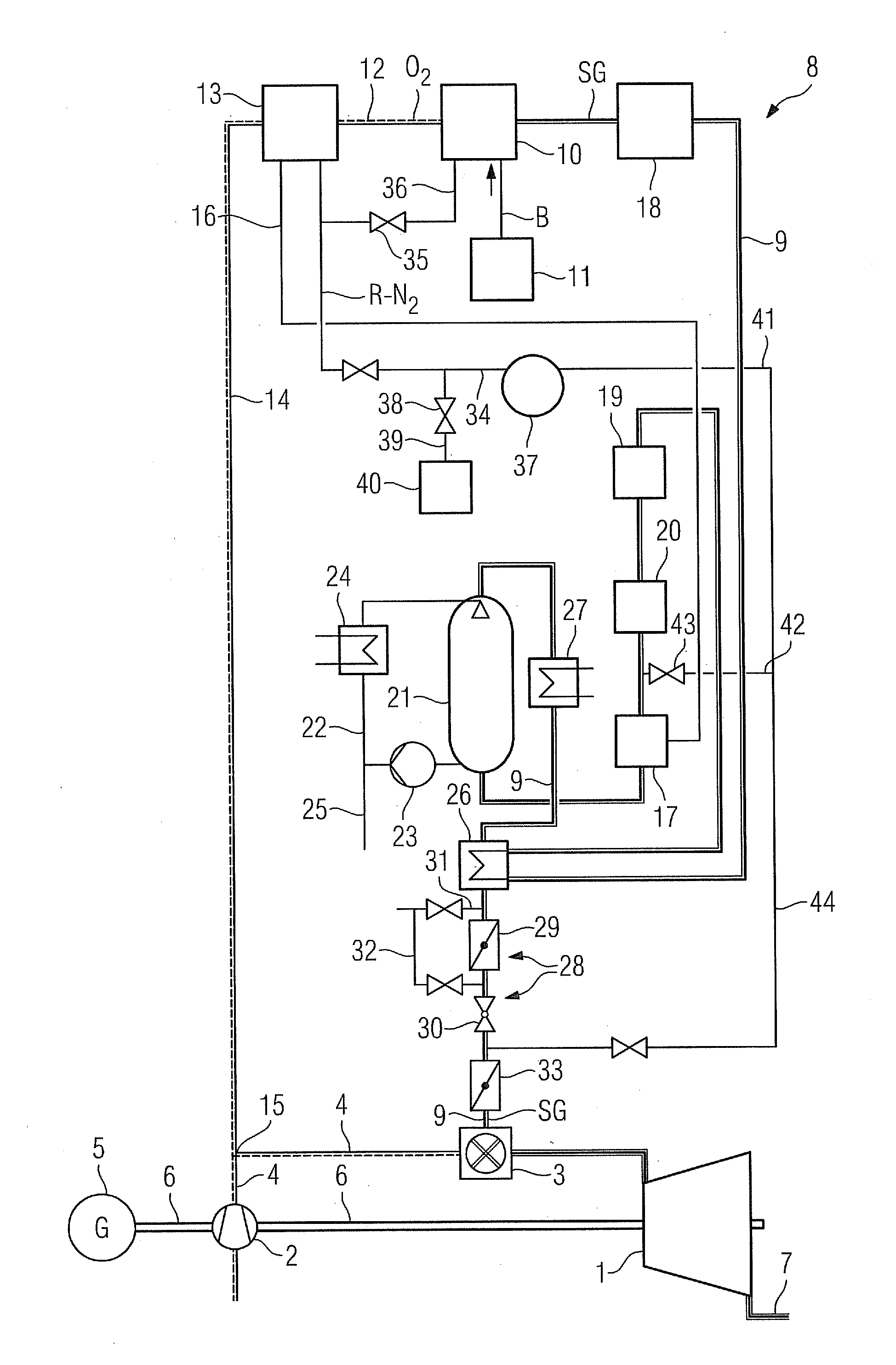
A combined cycle power plant includes a gas turbine system in accordance with the figure and a steam turbine system (not shown). The gas turbine system includes a gas turbine 1 with coupled air compressor 2 and a combustion chamber 3 connected upstream from the gas turbine 1, which is connected to a compressed air line 4 of the compressor 2. The gas turbine 1 and the air compressor 2 and also a generator 5 are attached to a common shaft 6. For feeding working medium or flue gas expanded in the gas turbine 1 into the waste heat steam generator of the steam turbine system an exhaust gas line 7 is connected to an output of the gas turbine 1.

The gas turbine system is designed for operation with a gasified natural gas or syngas SG, that is created by the gasification of a fossil fuel B. Gasified coal or gasified oil can be typically provided as syngas. To this end the gas turbine system includes a fuel system 8, via which syngas is able to be supplied to the combustion chamber 3 of the g...


PUM


Abstract

A combined cycle power plant with integrated coal gasification is provided. The power plant includes a gas turbine, a fuel system connected upstream of a combustion chamber of the gas turbine, which includes a gasification device for fossil fuel and a gas line branching off from the gasification device and opening out into the combustion chamber of the gas turbine, whereby a saturator for saturating the fuel with steam is connected into the gas line upstream of the combustion chamber, whereby a flushing line is provided which opens into the gas line between the gasification device and saturator.

Description

CROSS REFERENCE TO RELATED APPLICATIONSThis application claims priority of European Patent Office application. No. 10166084.3 EP filed Jun. 16, 2010, which is incorporated by reference herein in its entirety.FIELD OF INVENTIONThe invention relates to a combined cycle power plant with a gasification device for fossil fuel and a corresponding synthetic gas fuel system, as well as to a method for flushing out the synthetic gas fuel system of such a plant.BACKGROUND OF INVENTIONThe task of the synthetic gas fuel system is to prepare a syngas obtained from a gasification of a fuel (e.g. coal) and subsequently cleaned for combustion in a gas turbine (in accordance with the gas turbine requirements). To enable the system to be put into operation in an orderly manner and to enable repairs to be carried out after failures / faults, there is the need to render the system inert.In known IGCC plants (IGCC=integrated gasification combined cycle) the inerting is undertaken with the aid of steam as ...

Claims


Application Information

Patent Timeline
Patent Type & Authority Applications(United States)
IPC IPC(8): F02C1/00F02C6/00
CPCF01K23/068F02C3/28F02C6/18Y02E20/16F23K2301/203Y02E20/18F02C7/30F23K2300/203F02B43/08F02C7/00F02C7/22F02C7/232F23D2209/30
Inventor KEYSER, JENSREIMUTH, OLIVERSCHIFFERS, ULRICH
Owner SIEMENS AG
Why Eureka
Try Eureka