Internal combustion engine with fuel system

a fuel system and internal combustion engine technology, applied in the direction of liquid fuel feeders, machines/engines, mechanical apparatus, etc., can solve the problems of vapor bubble formation, vapor bubble formation in the fuel valve, and difficulty in starting the internal combustion engine or even preventing the engine from starting, etc., to achieve the effect of simple configuration and effective priming action

Active Publication Date: 2017-01-03
ANDREAS STIHL AG & CO KG
View PDF59 Cites 0 Cited by
  • Summary
  • Abstract
  • Description
  • Claims
  • Application Information

AI Technical Summary

Benefits of technology

[0007]In order to flush out vapor bubbles that are formed within the fuel system, it is provided that the conveying pump is arranged in a feed line into the fuel chamber of the fuel valve and conveys the fuel into the fuel chamber of the fuel valve. The fuel chamber is connected with a relief line in which a first valve is arranged. Since the fuel chamber of the fuel valve is flushed or primed, it is ensured that vapor bubbles in the fuel system are flushed out. At the same time, by priming the fuel valve with fuel, an effective cooling action of the fuel valve is achieved in a simple way and this prevents new vapor bubbles from being formed. By means of the first valve that is arranged in the relief line, the desired pressure in the fuel system can be maintained in operation. Depending on the control action and configuration of the first valve, priming of the fuel chamber in the injection valve can be done at a pressure significantly higher than operating pressure in the fuel system. In this way, an effective priming action and removal of gas or vapor bubbles, possibly contained in the fuel chamber, is enabled and this prevents new vapor bubbles from being formed.
[0008]A simple configuration results when the feed line in which the conveying pump is arranged is positioned in the flow path from a pump chamber of the fuel pump into the fuel chamber. The conveying pump can therefore be arranged in a feed line of the fuel system that is existing anyway. Advantageously, a pressure regulator is arranged downstream of the fuel pump. The feed line in which the conveying pump is arranged connects a control chamber of the pressure regulator with the fuel chamber. Since the conveying pump is arranged downstream of the pressure regulator, the pressure regulator does not act to limit the pressure that is supplied by the conveying pump for priming the fuel valve so that by means of the conveying pump a fuel pressure can be generated in the fuel system that is significantly higher than the fuel pressure that is conventionally existing in operation. However, it can also be provided that the feed line is a bypass line bypassing the fuel pump and connecting the fuel tank with the fuel chamber. As a result of the arrangement of the fuel pump in a bypass line bypassing the fuel pump, the spatial arrangement of the conveying pump relative to the fuel pump and the internal combustion engine can be substantially freely selected.
[0009]Advantageously, the first valve is actuated as a function of a pressure, i.e. is opened or closed by pressure control. The actuating pressure at which, when it is surpassed, the first valve opens is advantageously higher than the operating pressure of the fuel system. Accordingly, by means of the conveying pump a limited overpressure can be generated in the fuel system relative to normal operating pressure. In this way, it is prevented that new vapor bubbles can form in the fuel valve of the fuel system. The valve can open in particular as a function of the pressure in the fuel chamber or as a function of the pressure difference between fuel chamber and fuel tank. As an alternative or in addition, it can be provided that the valve is actuated as a function of temperature. The actuating temperature can be, for example, the temperature of the fuel valve or of the internal combustion engine. It can also be provided that the valve opens and closes as a function of the engine speed of the internal combustion engine. In this context, it is in particular provided that the valve is closed above a predetermined actuating engine speed so that the first valve in usual operation is closed and is open only during the starting process. It can also be provided that the first valve is closed once the first combustion cycle has been detected. The first combustion cycle can be, for example, detected based on the engine speed of the internal combustion engine. The actuating engine speed at which the valve is closed can be an engine speed that is reached as soon as the internal combustion engine has started and that is, however, below the idle speed of the internal combustion engine. As an alternative or in addition, it can be provided that the valve is actuated by time control. The first valve closes in this connection advantageously after lapse of a predetermined time span, for example, the time for one or several pull strokes for starting the engine. In this way, the fuel system is primed during the starting procedure. The different parameters for actuating the first valve can be combined in a suitable way.
[0010]A simple configuration results when the valve is a pressure retention valve that opens in the relief direction. The pressure retention valve operates mechanically so that for control of the pressure retention valve no additional devices are required. Since the first valve opens only in the relief direction, opening in the direction opposite to the relief direction, i.e., in the flow direction from the fuel tank to the fuel chamber, is prevented, for example, when in the fuel tank a higher pressure exists than in the fuel chamber. This is the case in particular in fuel systems in which the fuel tank is loaded with pressure. Advantageously, the first valve is an electrically actuated valve. The internal combustion engine has in particular an electronic control unit that actuates the first valve. In this way, an advantageous control of the first valve can be achieved that in particular takes into consideration several parameters.
[0011]It can be provided that a second valve is arranged in a bypass line bypassing the first valve. Advantageously, the second valve is a pressure retention valve while the first valve is an electrically actuated valve. By means of the pressure retention valve that is arranged in the bypass line, independent of the parameters that are used for actuating the first valve, it can be ensured that pressure in the fuel system does not rise impermissibly.

Problems solved by technology

It has been found that in fuel systems with a fuel valve, vapor bubble formation in the fuel system and in the injection valve makes it very difficult to start the internal combustion engine, or even prevents starting the engine.
The vapor bubble formation is a problem primarily in fuel systems that operate at minimal pressure, for example, a pressure of only one or several tenth of a bar, or a few bar, above ambient pressure.
When the fuel valve heats up too much, vapor bubbles can form in the fuel valve.
The vapor bubble formation is in particular also a problem when the internal combustion engine is shut off and after-heating occurs because no cooling air is conveyed anymore.

Method used


Image

  • Internal combustion engine with fuel system
  • Internal combustion engine with fuel system
  • Internal combustion engine with fuel system

Examples


Embodiment Construction

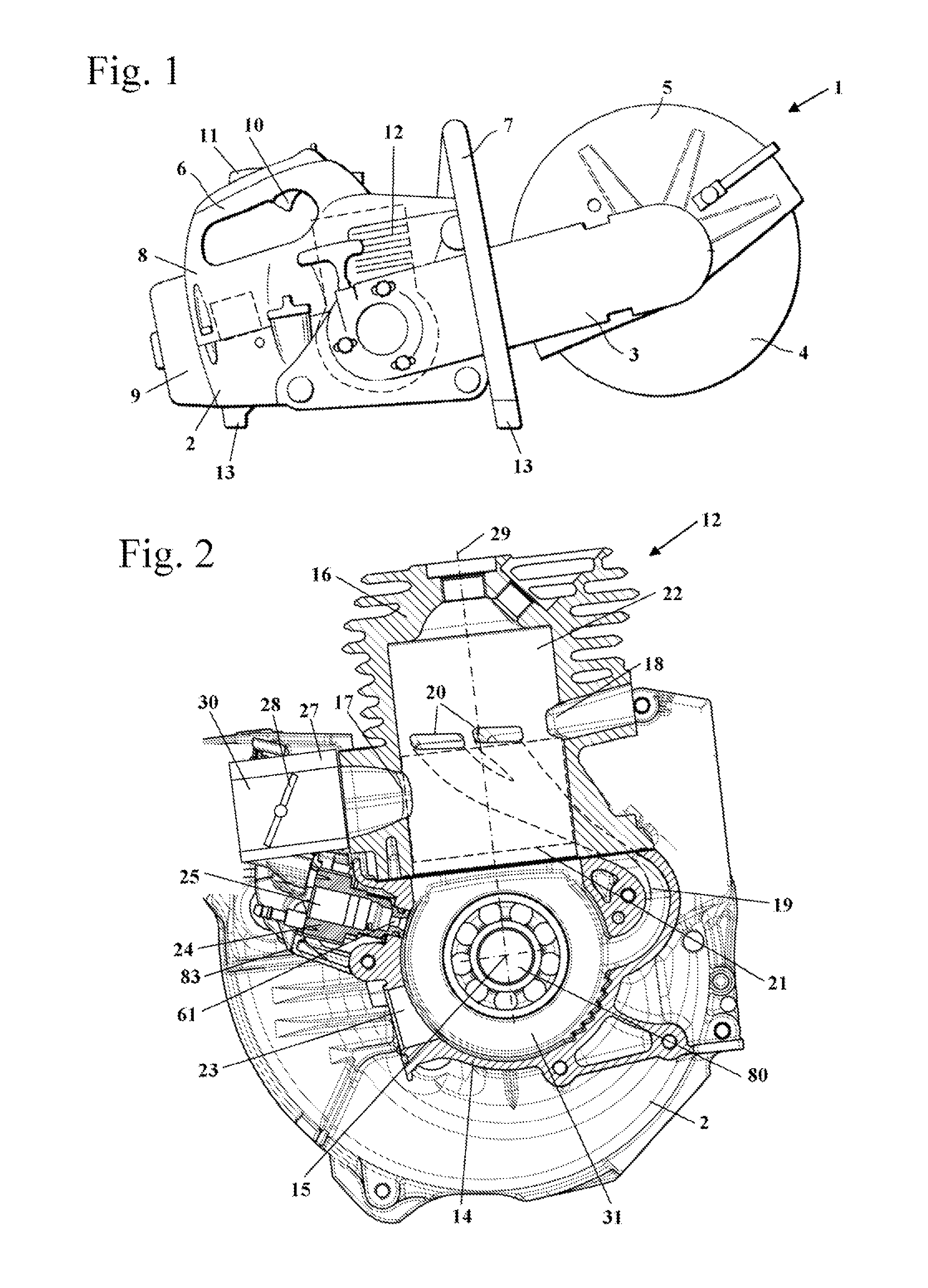
[0023]FIG. 1 shows an embodiment of a hand-guided power tool in the form of a cut-off machine 1. Instead of being used in the cut-off machine 1, the fuel system according to the invention can also be used in connection with other hand-guided power tools such as trimmers, motor chainsaws, blowers and the like. The cut-off machine 1 has a housing 2 in which an internal combustion engine 12 is arranged. On the housing 2, a cantilever arm 3 is secured that has at its free end a cutter wheel 4. The cutter wheel 4 is partially covered by a protective cover 5. The cutter wheel 4 is rotatingly driven by the internal combustion engine 12. For guiding the internal combustion engine 1, a top handle 6 as well as grip pipe (handlebar) 7 are provided. The handlebar 7 spans the housing 2 at the front side that is facing the cutter wheel 4. The top handle 6 is integrally formed on a hood 8 of the housing 2. On the top handle 6 a throttle trigger 10 and a throttle lock 11 are pivotably supported. At...


PUM


Abstract

An internal combustion engine has a fuel system that has a fuel valve with a housing, wherein in the housing a fuel chamber is formed. A fuel pump pumps fuel from a fuel tank into the fuel chamber. A conveying pump provides forced conveyance of fuel into the fuel system. A feed line is connected to the fuel chamber of the fuel valve. The conveying pump is arranged in the feed line and supplies fuel to the fuel chamber. A relief line is connected to the fuel chamber of the fuel valve and a first valve is arranged in the relief line.

Description

BACKGROUND OF THE INVENTION[0001]The invention relates to an internal combustion engine with a fuel system, wherein the fuel system comprises a fuel valve, wherein the fuel valve has a housing in which a fuel chamber is formed. The fuel system comprises a fuel pump that conveys fuel from the fuel tank into the fuel chamber. The fuel system has a conveying pump for forced conveyance of fuel into the fuel system.[0002]It is known to provide a conveying pump in fuel systems that operate with a carburetor, wherein the conveying pump is operated manually and primes the fuel system before starting the internal combustion engine, for example, after a longer shutdown period of the internal combustion engine. Such systems operate usually by suction. In such a system, the fuel is sucked in through the control chamber of the carburetor by the conveying pump that is arranged downstream of the carburetor. Such a system is disclosed, for example, in U.S. Pat. No. 6,938,884.[0003]In fuel systems t...

Claims


Application Information

Patent Timeline
Patent Type & Authority Patents(United States)
IPC IPC(8): F02M1/00F02B15/00F02M37/20F02M37/18F02M1/16F02M37/16F02M37/00F02M69/10
CPCF02B15/00F02M1/16F02M37/007F02M37/0023F02M37/0029F02M37/16F02M37/18F02M37/20F02M69/10
Inventor OSBURG, GERHARDKLATT, CLEMENSLEOPOLD, TOBIASDIETENBERGER, MICHAELLAYHER, WOLFGANG
Owner ANDREAS STIHL AG & CO KG
Why Eureka
Try Eureka