Method and apparatus for cooling system failure detection

a technology of cooling system and detection method, applied in the field of cooling system, can solve the problems of limiting the operating range, increasing cost, increasing size and/or weight,

Inactive Publication Date: 2006-02-02
SIEMENS VDO AUTOMOTIVE CORP
View PDF16 Cites 86 Cited by
  • Summary
  • Abstract
  • Description
  • Claims
  • Application Information

AI Technical Summary

Benefits of technology

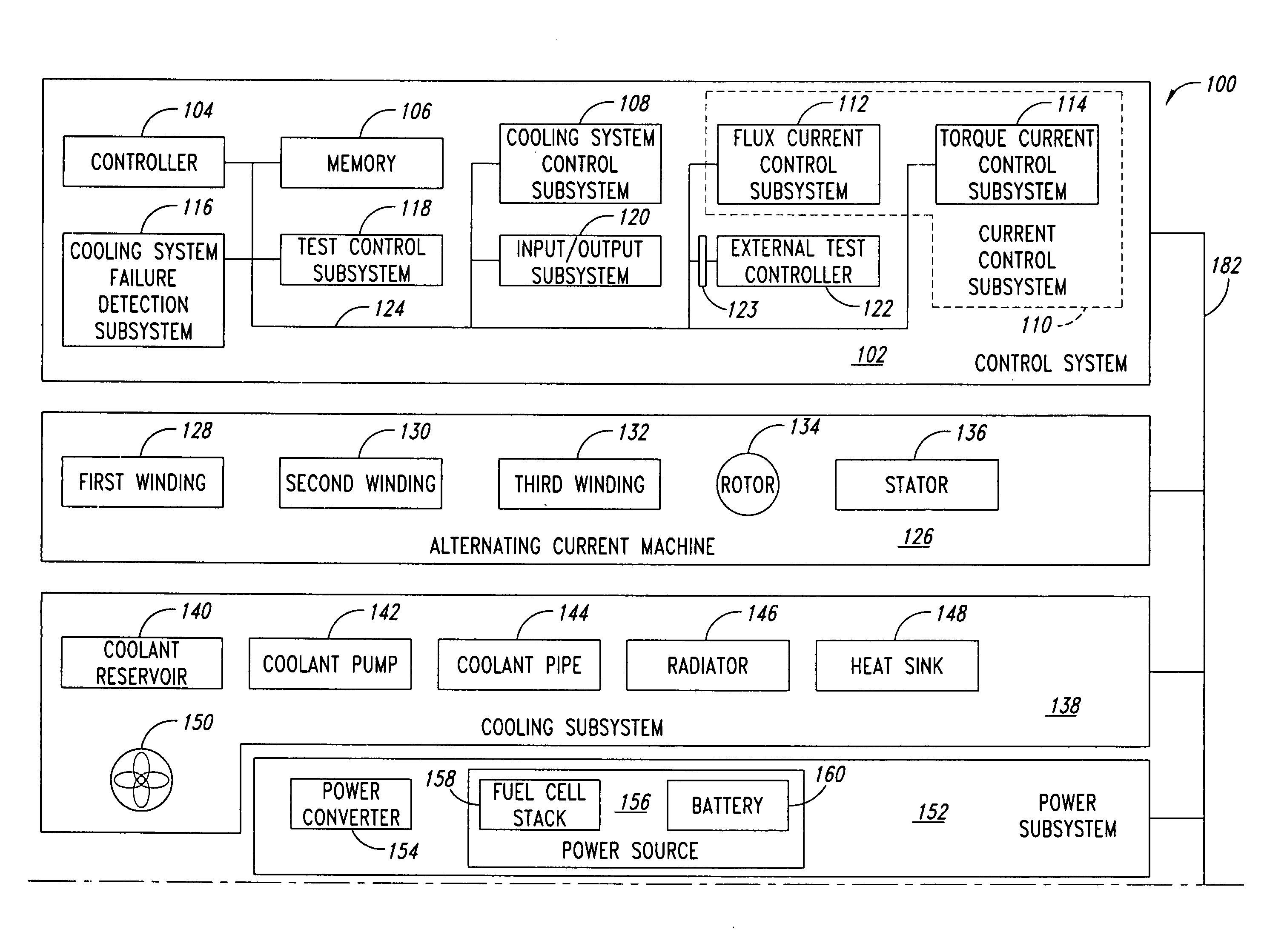
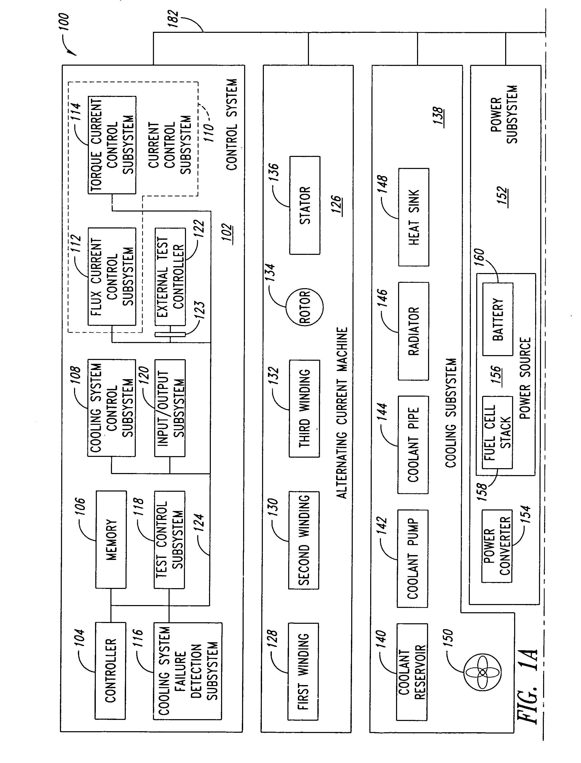
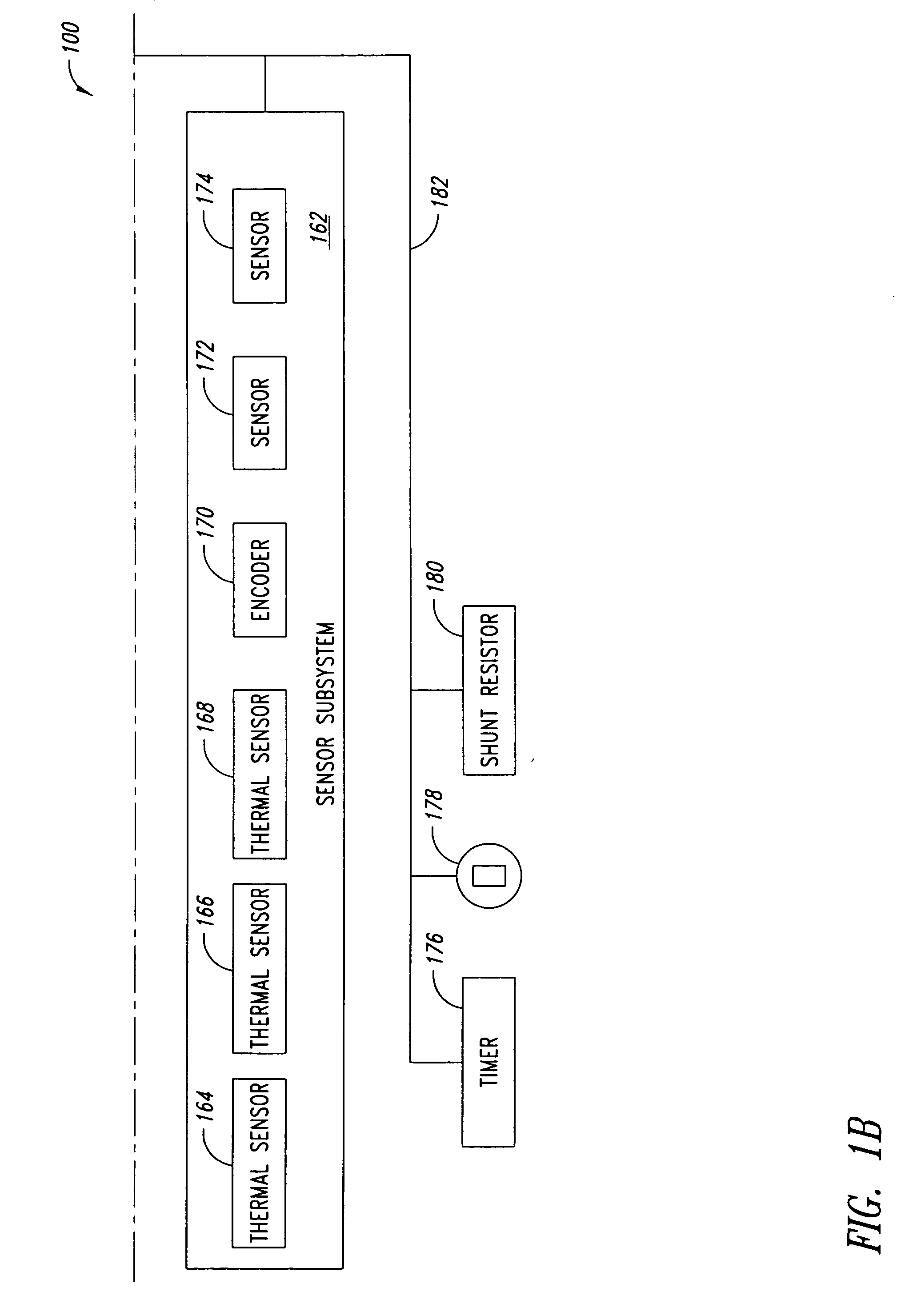
[0007] In one aspect, a control system for controlling an alternating current machine comprises: a current control subsystem to generate current control signals; a cooling system control subsystem to generate cooling system control signals; a sensor system to sense an operating condition of the machine; and a cooling system failure detection subsystem communicatively coupled to the current control subsystem, the cooling system control subsystem and the sensor system, wherein the cooling system failure detection subsystem is configured to: selectively initiate a cooling system failure detection cycle; generate a control signal to cause generation of waste heat in the machine during the cooling system failure detectio

Problems solved by technology

These power semiconductor devices dissipate large amounts of heat during high power operation, creating thermal management problems which may limit the operating range, increase cost, increase size and/or weight, adversely effect efficiency, and/or reduce reliability of the power subsystem.
This heat can cause the components to fail, and thus must be addressed.
Coo

Method used


Image

  • Method and apparatus for cooling system failure detection
  • Method and apparatus for cooling system failure detection
  • Method and apparatus for cooling system failure detection

Examples


Embodiment Construction

[0018] In the following description, certain specific details are set forth in order to provide a thorough understanding of various embodiments. However, one skilled in the art will understand that the present systems and methods may be practiced without these details. In other instances, well-known structures associated with cooling systems, power subsystems, bus systems, controllers, gate drivers, and / or alternating current machines have not been shown or described in detail to avoid unnecessarily obscuring descriptions of the embodiments.

[0019] Unless the context requires otherwise, throughout the specification and claims which follow, the word “comprise” and variations thereof, such as, “comprises” and “comprising” are to be construed in an open sense, that is as “including, but not limited to.”

[0020] Reference throughout this specification to “one embodiment” or “an embodiment” means that a particular feature, structure or characteristic described in connection with the embodi...


PUM


Abstract

A system and method for detecting failure of a cooling system in an alternating current machine, such as a motor and/or a generator. For example, in one embodiment energy wasting is initiated and a failure is indicated if a temperature rises by more than a selected amount over a selected time period.

Description

BACKGROUND OF THE INVENTION [0001] 1. Field of the Invention [0002] This disclosure generally relates to cooling systems for machines including induction motors and / or generators, and more particularly to a system and method for detecting a cooling system failure. [0003] 2. Description of the Related Art [0004] The “fuel” powering an alternating current machine, such as a field-oriented induction motor, is current. This current may be divided into two components, torque current and flux current. Torque current may be viewed as that component of the current that generates motive force, or torque. Flux current may be viewed as that component of the current that generates magnetic flux in the rotor of the machine. Torque and flux currents in induction motors are discussed in more detail in co-pending U.S. patent application Ser. No. 10 / 345,872, filed Jan. 15, 2003, and entitled “OVERMODULATION SYSTEMS AND METHODS FOR INDUCTION MOTOR CONTROL” and in a February 1998 publication by Texas ...

Claims


Application Information

Patent Timeline
IPC IPC(8): F25B49/00G01K13/00
CPCF25B49/005H02P29/02H02K9/24
Inventor NALLAPA, VENKATAPATHI RAJU
Owner SIEMENS VDO AUTOMOTIVE CORP
Why Eureka
Try Eureka