Tire sealant injector

Inactive Publication Date: 2006-02-02
RAGAN PHILIP J +1
View PDF4 Cites 20 Cited by
  • Summary
  • Abstract
  • Description
  • Claims
  • Application Information

AI Technical Summary

Benefits of technology

[0004] The present invention allows for a controlled, measured amount of sealant to be injected into the tire with out the mess and waste of the conventional systems known today. The U.S. Pat. No. 5,908,145 to Jaksa show a typical system for injecting sealing fluid into a tire which includes a valve stem connector, reservoir chamber and a flexible hose connecting the two. Jaksa also shows a set of fittings which connect to a source of compressed air or pump to inject the sealant into the tire. The invention of Jaksa is both more costly than the present invention and relies on an outside agent (compressed air from a pump or compressor) to inject the sealing fluid into the tire. This is a typical construction for many of the prior art documents in this field. It should also be pointed out that the device of Jaksa makes no provision for servicing both Schrader and Presta type valve stems. The U.S. Pat. No. 5,012,954 to Will shows a tire inflation system using a compressed gas to fill a tire with air. Will does not make any attempt to fix a puncture but rather a way of inflating a brand new tube when positioned within a tire. The only significant thing in this patent is that an adapter is used to accommodate both Schrader and Presta type valve stems.
[0005] It is an object of the present invention to provide a simple, efficient and cost effective device for injecting tire sealant into a tire.
[0006] It is another object of the present invention to provide a way of sealing a puncture in a tire without wasting tire sealant and also providing a way to measure and control the amount of sealant being injected into the tire.
[0007] It is a further object of the invention to allow for all skill levels of user to effectively use the invention and not to have to rely upon external sources for successful completion of the sealant insertion.
[0008] The following description comprises an improved mechanism for injecting tire seal

Problems solved by technology

The shortcoming of the known aerosol type or “fix a flat” type of devices is that there is no way of knowing

Method used


Image

  • Tire sealant injector
  • Tire sealant injector
  • Tire sealant injector

Examples


Embodiment Construction

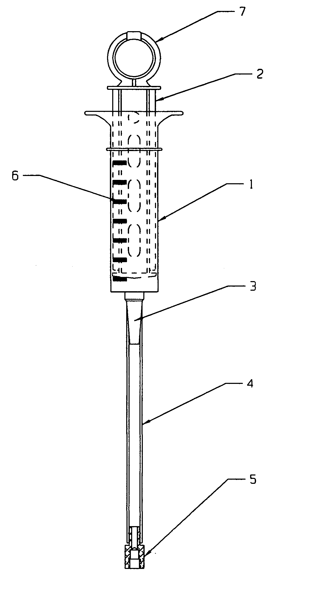
[0014] In FIG. 1, the elements shown are arranged in a preferred form. Sealant reservoir 1 has a plunger mechanism 2 positioned within its chamber. The plunger mechanism is shown to have a ring type end 7 but it should be stated that any type of end can be used. The outer walls of the sealant reservoir 1 have level indicator markings 6 so as to aid in achieving the proper filling level depending upon the size and style of the tire to be filled. The sealant reservoir 1 is that of a syringe type whereas the outer syringe forms the reservoir and the plunger mechanism 2 acts to both draw the sealant from its container and to expel the sealant through the hose connector 3 positioned at the sealant reservoir end. Connected to the hose connector 3 is a flexible hose or tubing 4. It is preferable that the tubing 4 is clear so as to make sure all the sealant has been dispensed but the tubing 4 can be opaque. While size, shape and color are not critical to the functioning of the sealant injec...


PUM

PropertyMeasurementUnit
Flexibilityaaaaaaaaaa
Areaaaaaaaaaaa

Abstract

The invention relates to a device for injecting tire sealant fluid into a tire. The present invention uses a syringe type reservoir connected to a long, flexible tube which is in turn connected to a valve stem connector. The valve stem connector has two different threads, Schrader and Presta, to accommodate both types of valve stems. The Schrader type threads are larger than the Presta type threads and thus the Presta type threads are positioned further into the valve stem connector of the present invention than the Schrader type threads. The larger Schrader type threads are used on automobiles and less expensive bicycles. The Presta threads are more common in Europe and are used on most high-performance bicycles. The main advantages of the present invention are that an exact amount of sealant can be dispensed, there is no wasted sealant because spillage is eliminated and the device uses no external power source to dispense the sealant. The tire sealant injector can be used on bicycles, utility vehicles, ATVs, lawn and garden tractors, wheelbarrows, golf carts and even automobiles

Description

FIELD OF THE INVENTION [0001] The invention relates to a syringe type injector for dispensing tire puncture sealant into a tire. The invention is used to both seal a tire puncture and also to help prevent future tire punctures and leaks. BACKGROUND OF THE INVENTION [0002] The present invention solves many problems that face any type of tire repair as it relates to punctures and leaks. Originally he field of bicycling was the primary field of use for the present invention. It was determined that a variety of other applications includes also well within the scope of the present invention. Other applications could include: ATV's, utility vehicles, lawn and garden tractors, wheelbarrows, golf carts and automobiles but are not limited to those listed. The invention grew out a need for a simple, more accurate and less messy way of injecting puncture sealant into a tire which has either lost its air or has otherwise become unable to hold the air which is put into it. A further development ...

Claims


Application Information

Patent Timeline
IPC IPC(8): B29C73/08
CPCB29L2030/00B29C73/166
Inventor RAGAN, PHILIP J.RAGAN, BRANDON
Owner RAGAN PHILIP J
Why Eureka
Try Eureka