Multi-gas distribution injector for chemical vapor deposition reactors

a technology of chemical vapor deposition reactor and injector, which is applied in chemical vapor deposition coating, coating, metal material coating process, etc., can solve the problems of recirculation pattern near the injector, interference with efficient operation or even deposition, and unwanted deposition of reactants on the injector inl

Inactive Publication Date: 2006-02-02
VEECO INSTR
View PDF99 Cites 360 Cited by
  • Summary
  • Abstract
  • Description
  • Claims
  • Application Information

AI Technical Summary

Benefits of technology

[0015] A method of chemical vapor deposition according to one aspect of the invention includes discharging at least one precursor gas as a plurality of streams into a reaction chamber through a plurality of spaced-apart precursor inlets in a gas distribution injector so that the streams have a component of velocity in a downstream direction away from the injector towards one or more substrates disposed in the chamber, the at least one precursor gas reacting to form a reaction deposit on the one or more substrates; and, simultaneously, discharging at least one carrier gas sub

Problems solved by technology

However, many existing gas injector systems have problems that may interfere with efficient operation or even deposition.
For example, precursor injection patterns in existing gas distribution injector systems may contain significant “dead space” (space without active flow from gas inlets on the injector surface) resulting in recirculation patterns near the injector.
These recirculation patterns may result in prereaction of the precursor chemicals, causing unwanted deposition of reactants on the injector inlets (referred to herein as “reverse jetting”).
This can also result in lower efficiency and memory effects.
However, systems requiring a large number of inlets sometimes occasion difficulties in manufacture and consistency.
This greater inlet density may, in some configurations, result in penetration of precursor from one inlet into another, clogging the inlets with parasitic reaction products from interaction of the precursors.
Also, an injector design with small distances between inlets may not, in some configurations, allow enough space for the optical viewports required for many types of in-situ characterization devices frequently required in modern MOCVD equipment.
In addition, the diff

Method used


Image

  • Multi-gas distribution injector for chemical vapor deposition reactors
  • Multi-gas distribution injector for chemical vapor deposition reactors
  • Multi-gas distribution injector for chemical vapor deposition reactors

Examples


Embodiment Construction

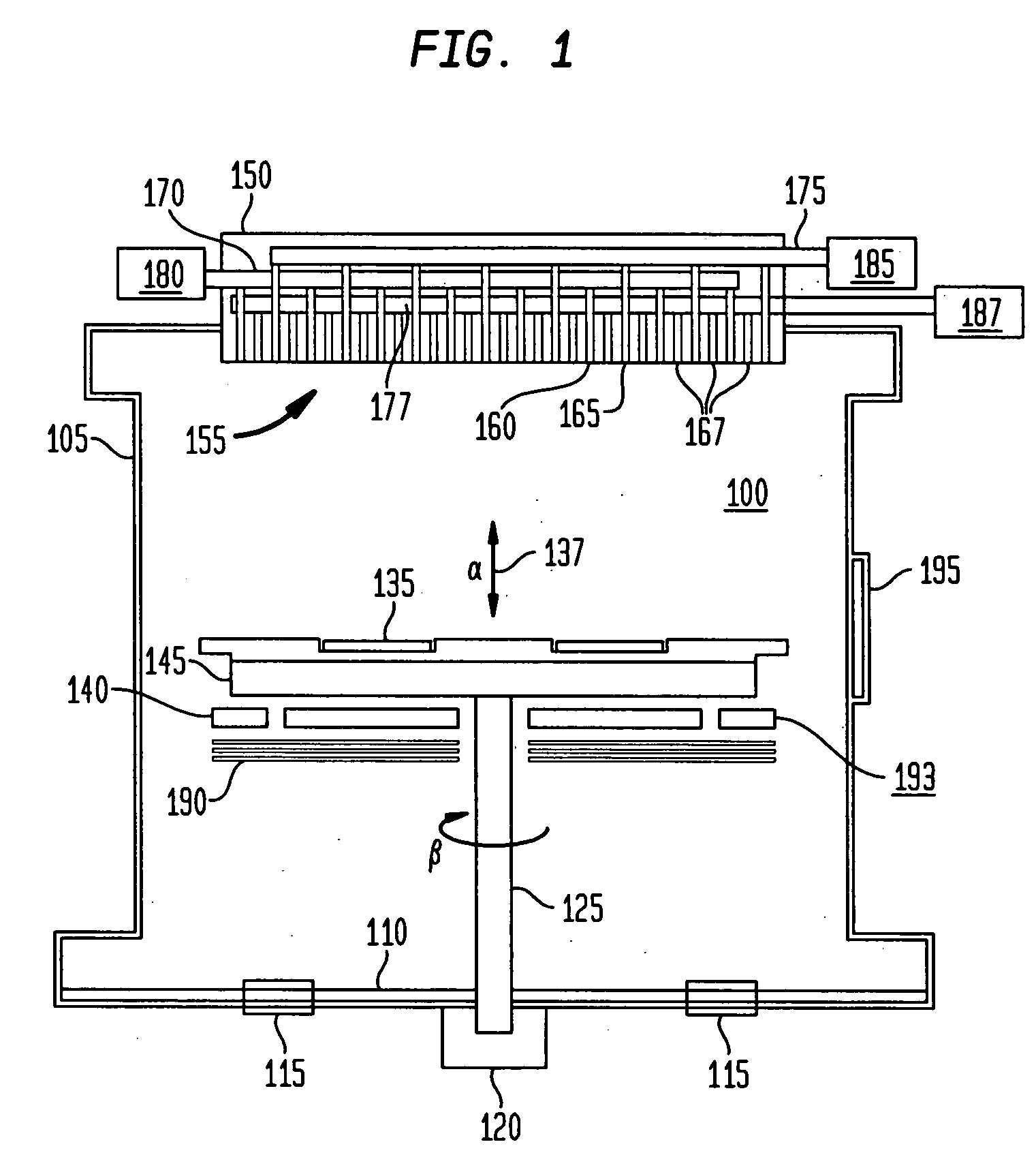
[0058] Referring now to the drawings wherein like numerals indicate like elements, FIG. 1 shows a rotating disk reactor incorporating a multi-gas injector according to one embodiment of the present invention.

[0059] As diagrammatically shown in FIG. 1, the apparatus includes a cylindrical reaction chamber 100 made of stainless steel walls 105, a base plate 110, exhaust ports 115, and a rotating vacuum feedthrough 120 that seals rotating spindle 125, on top of which is installed a wafer carrier 130 with substrate wafers 135. The wafer carrier is rotatable about an axis 137 (α), coaxial with cylindrical chamber 100, at a predetermined rotation rate (β).

[0060] A heating susceptor 145 is heated by a set of heating elements 140, typically made from a refractive metal such as but not limited to, for example, molybdenum, tungsten or rhenium and the like, or a non-metal such as graphite, which may be divided into multiple heating zones. The metal for heating elements may be selected based ...


PUM

PropertyMeasurementUnit
Timeaaaaaaaaaa
Flow rateaaaaaaaaaa
Structureaaaaaaaaaa

Abstract

A gas distribution injector for chemical vapor deposition reactors has precursor gas inlets disposed at spaced-apart locations on an inner surface facing downstream toward a substrate carrier, and has carrier openings disposed between the precursor gas inlets. One or more precursor gases are introduced through the precursor gas inlets, and a carrier gas substantially nonreactive with the precursor gases is introduced through the carrier gas openings. The carrier gas minimizes deposit formation on the injector. The carrier gas openings may be provided by a porous plate defining the surface or via carrier inlets interspersed between precursor inlets. The gas inlets may removable or coaxial.

Description

CROSS-REFERENCE TO RELATED APPLICATIONS [0001] This application claims the benefit of the filing date of U.S. Provisional patent application No. 60 / 598,172, filed Aug. 2, 2004, the disclosure of which is hereby incorporated herein by reference.BACKGROUND OF THE INVENTION [0002] This invention relates to systems for reactive gas phase processing such as chemical vapor deposition, and is more specifically related to the structure of a multi-gas distribution injector for use in such reactors. [0003] Chemical vapor deposition (“CVD”) reactors permit the treatment of wafers mounted on a wafer carrier disposed inside a reaction chamber. A component referred to as a gas distribution injector, such as those sold by the assignee of the present application under the trademark FLOWFLANGE, is mounted facing towards the wafer carrier. The injector typically includes a plurality of gas inlets that provide some combination of one or more precursor gases to the chamber for chemical vapor deposition...

Claims


Application Information

Patent Timeline
IPC IPC(8): C23C16/00
CPCC23C16/45565C23C16/45574C23C16/45572C23C16/00
Inventor ARMOUR, ERIC A.GURARY, ALEXKADINSKI, LEVDOPPELHAMMER, ROBERTTOMPA, GARYKATS, MIKHAIL
Owner VEECO INSTR
Why Eureka
Try Eureka