Flow control for on-board inert gas generation system

Active Publication Date: 2006-02-02
HAMILTON SUNDSTRAND CORP
View PDF23 Cites 61 Cited by
  • Summary
  • Abstract
  • Description
  • Claims
  • Application Information

AI Technical Summary

Benefits of technology

[0006] An on-board inert gas generating system includes a flow control valve modulated accor

Problems solved by technology

Oxygen mixed with the fuel vapor within the ullage creates a potentially hazardous condition.
Such changes in the rate of flow of nitrogen-enriched air result in a change in the amount of oxygen within the fuel tank.
The fixed orifices used to control f

Method used


Image

  • Flow control for on-board inert gas generation system
  • Flow control for on-board inert gas generation system
  • Flow control for on-board inert gas generation system

Examples


Embodiment Construction

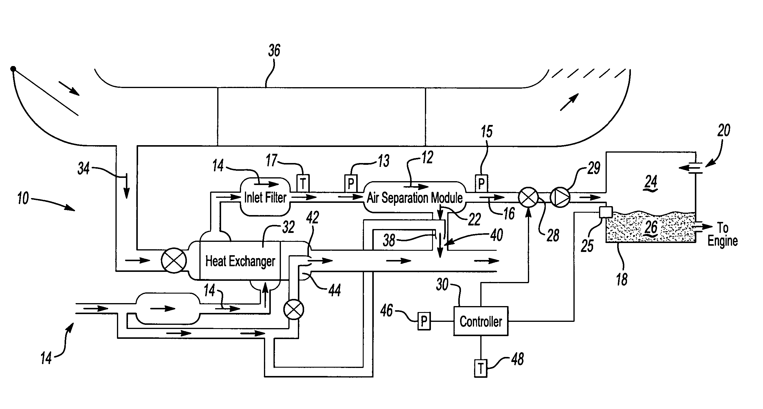
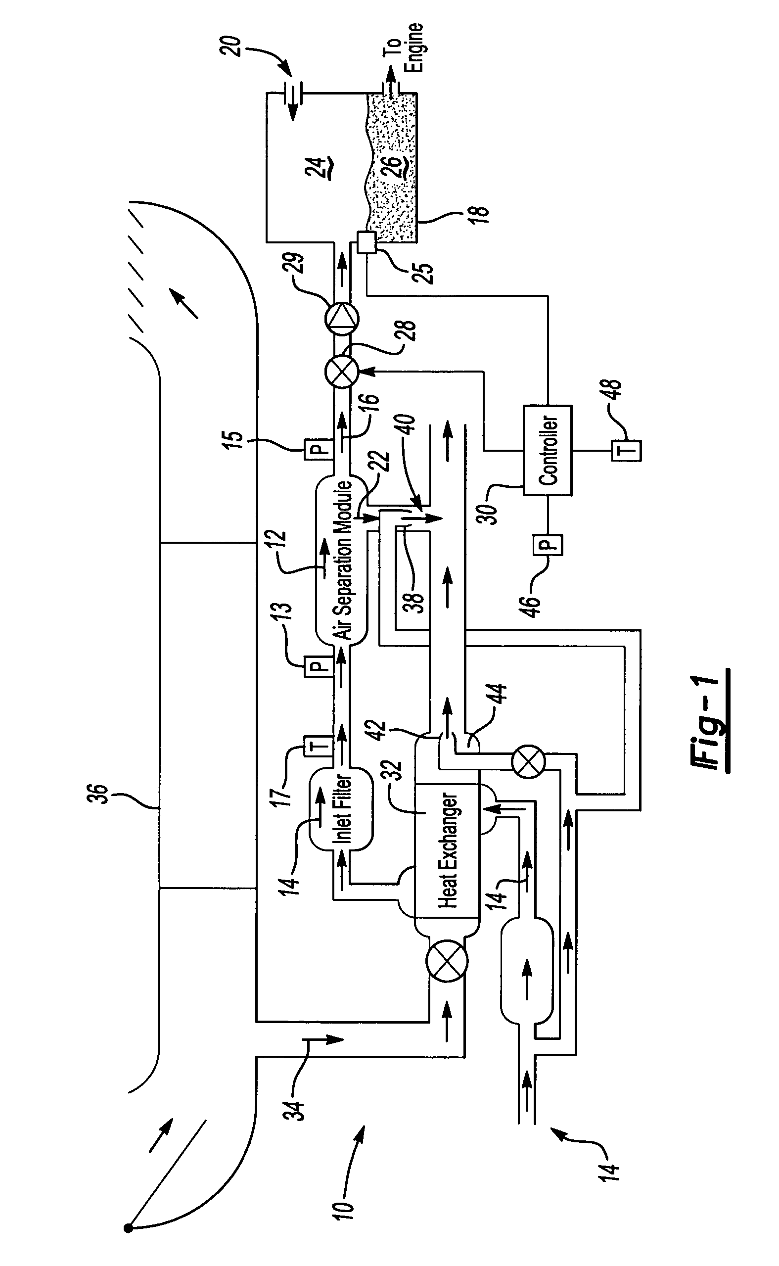
[0014] Referring to FIG. 1, an example of an on-board inert gas generating system (OBIGGS) 10 is shown and includes an air separation module 12 that removes oxygen from manifold bleed airflow 14. The air separation module 12 removes oxygen from the high pressure air stream 14 and supplies a nitrogen-enriched air stream 16 to a fuel tank 18. An oxygen stream 22 from the air separation module 12 is exhausted overboard. The example fuel tank 18 includes a vent 20 to the ambient environment. The vent 20 causes changes in pressure and temperature within the fuel tank 18 responsive to changes in ambient conditions.

[0015] The system 10 includes a heat exchanger 32 provided to regulate the temperature of the high pressure air stream 14. The example heat exchanger 32 exchanges heat between the bleed airflow 14 and ram airflow 34 drawn from a ram air passage 36. The ram airflow 34 moves at a relatively high flow rate as compared to the bleed airflow 14. The high flow rate of the ram airflow ...


PUM


Abstract

An on-board inert gas generating system includes a flow control valve modulated according to changes in ambient conditions to minimize changes to oxygen content within a fuel tank. The quality of the nitrogen-enriched air stream that is provided by the air separation module varies in response to flow. Higher flow rates through the air separation module removes less oxygen relative to lower flow rates. The amount of flow through the air separation module that produces the least amount of oxygen within the fuel tank is determined for an ambient pressure and provided by modulating the flow control valve.

Description

BACKGROUND OF THE INVENTION [0001] This invention relates to a fuel tank inerting system, and more particularly to a process and device for controlling oxygen content within a fuel tank. [0002] An aircraft fuel tank includes a liquid fuel filled portion and a fuel vapor filled portion known as the fuel tank ullage. Oxygen mixed with the fuel vapor within the ullage creates a potentially hazardous condition. Systems that replace oxygen-containing air with an inert gas substantially reduce the risks of this potentially hazardous condition. Some systems utilize tanks of nitrogen rich air for replacing the oxygen containing air within the fuel tank ullage. An on-board inert gas generating system that replaces oxygen rich air with nitrogen-enriched air is currently under development for use in aircraft. [0003] On-board inert gas generating systems utilize an air separation module that removes oxygen to produce a nitrogen-enriched air stream that fills the fuel tank ullage. Typically the ...

Claims


Application Information

Patent Timeline
IPC IPC(8): B67D5/54B64D37/32B67D7/72B65D90/44
CPCB65D90/44B64D37/32A62C3/08A62C99/0018Y10T137/3127Y10T137/0324
Inventor SURAWSKI, ERIC
Owner HAMILTON SUNDSTRAND CORP
Why Eureka
Try Eureka