Elastomeric vehicle control switch

a technology of elastomeric pads and switch banks, which is applied in the direction of emergency actuators, switches with three operating positions, road vehicles, etc., can solve the problems of insufficient structural strength of conventional switch banks, inability to provide tactile feedback to users, and inability to prevent both contacts

Inactive Publication Date: 2006-02-02
LEAR CORP
View PDF26 Cites 11 Cited by
  • Summary
  • Abstract
  • Description
  • Claims
  • Application Information

AI Technical Summary

Benefits of technology

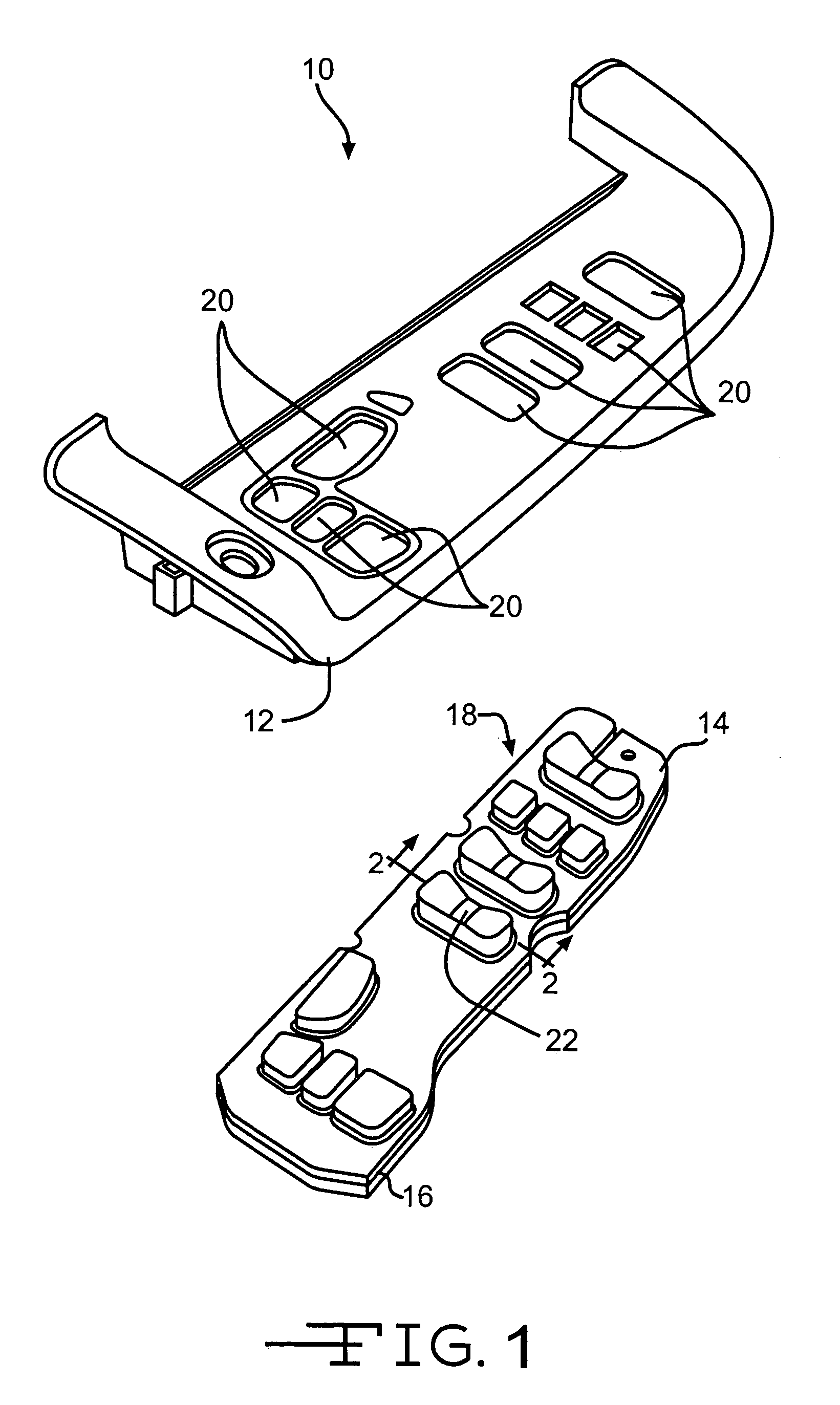
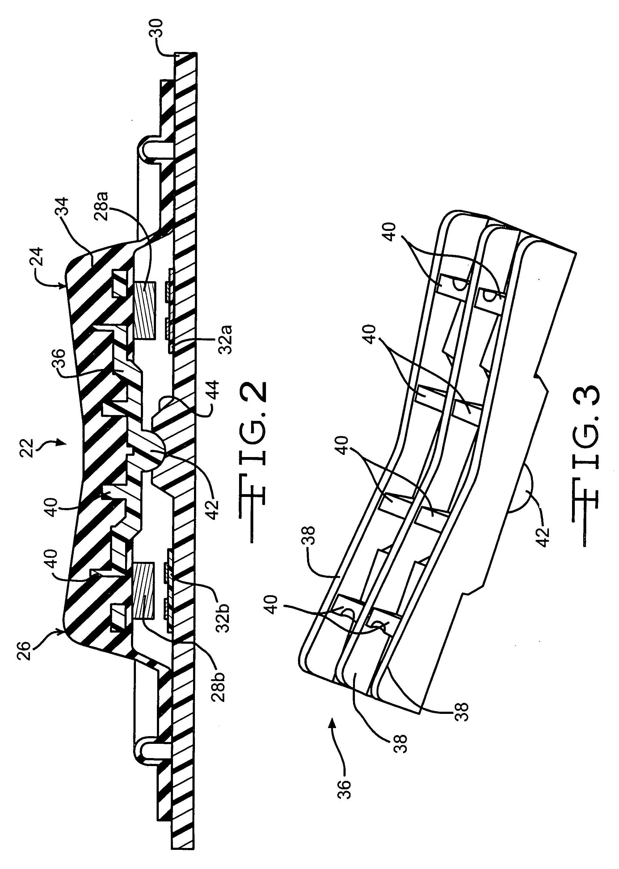
[0005] This invention relates to a vehicle control switch assembly for use with a printed circuit board. The switch assembly includes an elastomeric pad and a support member. The elastomeric pad has a contact pad for selective engagement with an electrical contact of the printed circuit board. The support member is molded together with the elastomeric pad.
[0006] The invention also relates to a vehicle control switch assembly. The assembly *includes a printed circuit board having an electrical contact, an elastomeric pad having a contact pad for selective engagement with the electrical contact of the printed circuit board, and a support member. The support member is positioned between the elastomeric pad and the printed circuit board to provide support for the elastomeric pad.

Problems solved by technology

The conventional switch bank has a number of deficiencies that include when the switch bank is manufactured, the layers (i.e., the overlay, the membrane, the spacer, the circuit board, and the sub-panel) can be difficult to align such that the respective symbols, holes, and circuits align properly, the switch bank is not lighted or backlit, the overlay and the symbols are not registered (i.e., the surface of the overlay is substantially smooth such that a user can not readily discern switch location and type by feel), and the switch bank does not provide tactile feedback feel to the user.
Additionally, conventional switch banks, particularly rocker type switches with opposed contacts for first and second functions lack sufficient structural strength to prevent both contacts from being made when multiple forces are applied.

Method used


Image

  • Elastomeric vehicle control switch
  • Elastomeric vehicle control switch
  • Elastomeric vehicle control switch

Examples


Embodiment Construction

[0013] Vehicle interior passenger compartments are, in large measure, conventional in the art. The typical vehicle interior passenger compartment includes an instrument panel or dashboard. The instrument panel may include control mechanisms and switches for various components of the vehicle, such as, temperature and climate controls system, audio and video systems, windows, seat and mirror positioning mechanisms, and navigational systems. These controls may be positioned within the instrument panel, a lower console, doors, or any other suitable location within the interior of the vehicle. Alternatively, a second storage compartment (not shown) may be provided in the back seat area and can also have various controls (climate, windows, video gaming device controls, audio controls, headphone jacks, etc.) located thereon. An overhead console (not shown) can also be accessible from within the interior passenger compartment of the vehicle. The overhead console can contain various controls...


PUM


Abstract

A vehicle control switch assembly for use with a printed circuit board is disclosed. The switch assembly includes an elastomeric pad and a support member. The elastomeric pad has a contact pad for selective engagement with an electrical contact of the printed circuit board. The support member is molded together with the elastomeric pad. A vehicle control switch assembly including a printed circuit board having an electrical contact, an elastomeric pad having a contact pad for selective engagement with the electrical contact of the printed circuit board, and a support member is also disclosed. The support member is positioned between the elastomeric pad and the printed circuit board to provide support for the elastomeric pad.

Description

BACKGROUND OF THE INVENTION [0001] This invention relates in general to vehicle control switch assemblies, and more specifically to control switches having an elastomeric pad. [0002] A conventional switch bank (or array) is typically formed having a stacked (i.e., overlaid) structure. The switch bank is implemented to carry a low voltage DC signal. The switch bank is a group of normally open, single pole, single throw (NO, SP, ST) momentary contact device switches. The switch bank can include a graphic overlay having painted or printed on symbols that relate to numbers, vehicle functions, and the like depending on the application of the switch bank. For example, the overlay is disposed over an electrostatic discharge (ESD) / electromagnetic interference (EMI) shield. In another example, the overlay is disposed directly over a top membrane or elastomeric pad. The membrane has a number of contacts that align with the respective symbols when the switch bank is properly assembled. [0003] ...

Claims


Application Information

Patent Timeline
Patent Type & Authority Applications(United States)
IPC IPC(8): H01H13/70H01H13/702H01H23/30
CPCH01H13/702H01H23/30H01H2231/026H01H2221/016H01H2219/062H01H13/70
Inventor SCHMIDT, ROBERT M.FELDMAN, MARK G.AMUNDSON, ROBERT
Owner LEAR CORP
Why Eureka
Try Eureka