Quick disconnect cryogenic coupler

a cryogenic coupler and quick disconnect technology, applied in the direction of couplings, respirators, container discharge methods, etc., can solve the problem that none of these prior art structures include the use of laterally severed tubular bushings, and achieve the effect of preventing icing

Active Publication Date: 2006-02-02
PARKER HANNIFIN CORP
View PDF8 Cites 20 Cited by
  • Summary
  • Abstract
  • Description
  • Claims
  • Application Information

AI Technical Summary

Benefits of technology

[0030] A differing version thereof, further includes a male nipple assembly releasably joined with the coupler via a further operative interconnection, with the further operative connection includes, in the nipple assembly, an inner end portion adapted to be inserted into the coupler via the coupler sleeve inlet portion and making a sealing contact with the inner peripheral surface of the annular interface seal and permitting the purging of the inlet portion and the adjacent nipple in

Problems solved by technology

However, none of these prior art structures include the use of a laterally severed tubular bushing th

Method used


Image

  • Quick disconnect cryogenic coupler
  • Quick disconnect cryogenic coupler
  • Quick disconnect cryogenic coupler

Examples


first embodiment

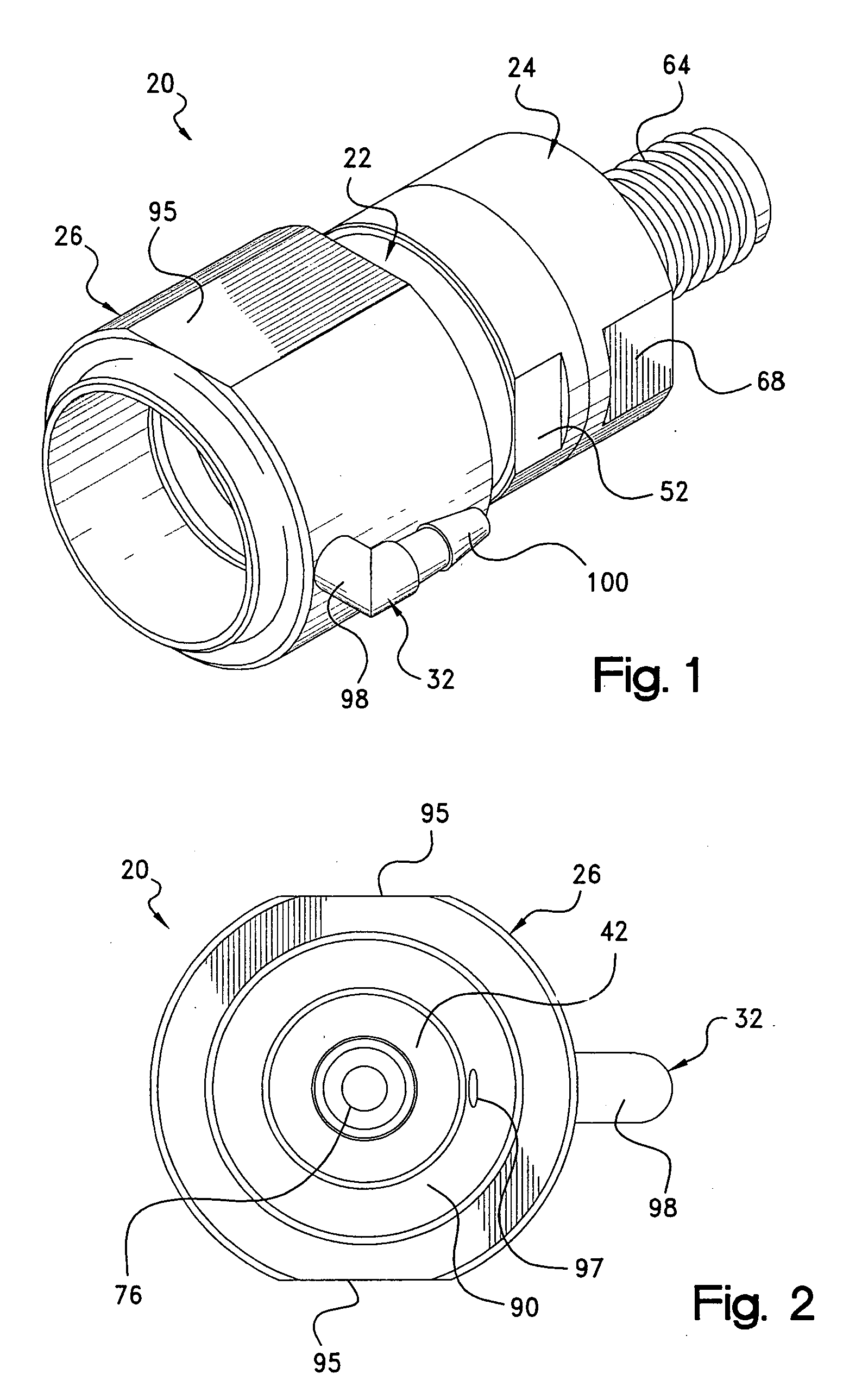
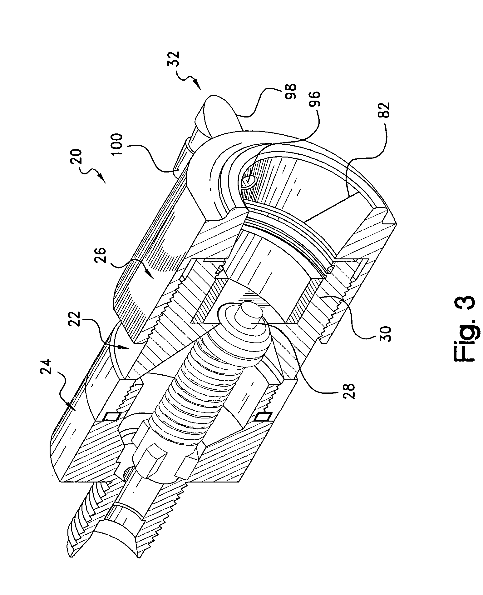
[0042] Referring now to the several drawings, illustrated in FIGS. 1-4 is the quick disconnect cryogenic coupler of the present invention, generally indicated at 20, with coupler 20 being basically comprised of the combination of at least five major components, namely: a coupler body 22, an adaptor 24, a coupling sleeve 26, a valve assembly 28, a split bushing 30 in coupler body 22; and an optional vent fitting 32 in coupling sleeve 26. Coupler 20 is adapted to be releasably connected with any desired, known, male nipple (not shown in this embodiment) in order to transfer the cryogenic fluid. It should be understood that with coupler 20, no separate device is utilized to for locking same to the male nipple, rather, coupler 20 is physically held onto the male nipple with an external force being applied to the unit (FIG. 9) in which coupler 20 is installed.

[0043] Specifically, coupler body 22, which is generally cylindrical in shape, has an exterior threaded portion 34 and a cylindric...

second embodiment

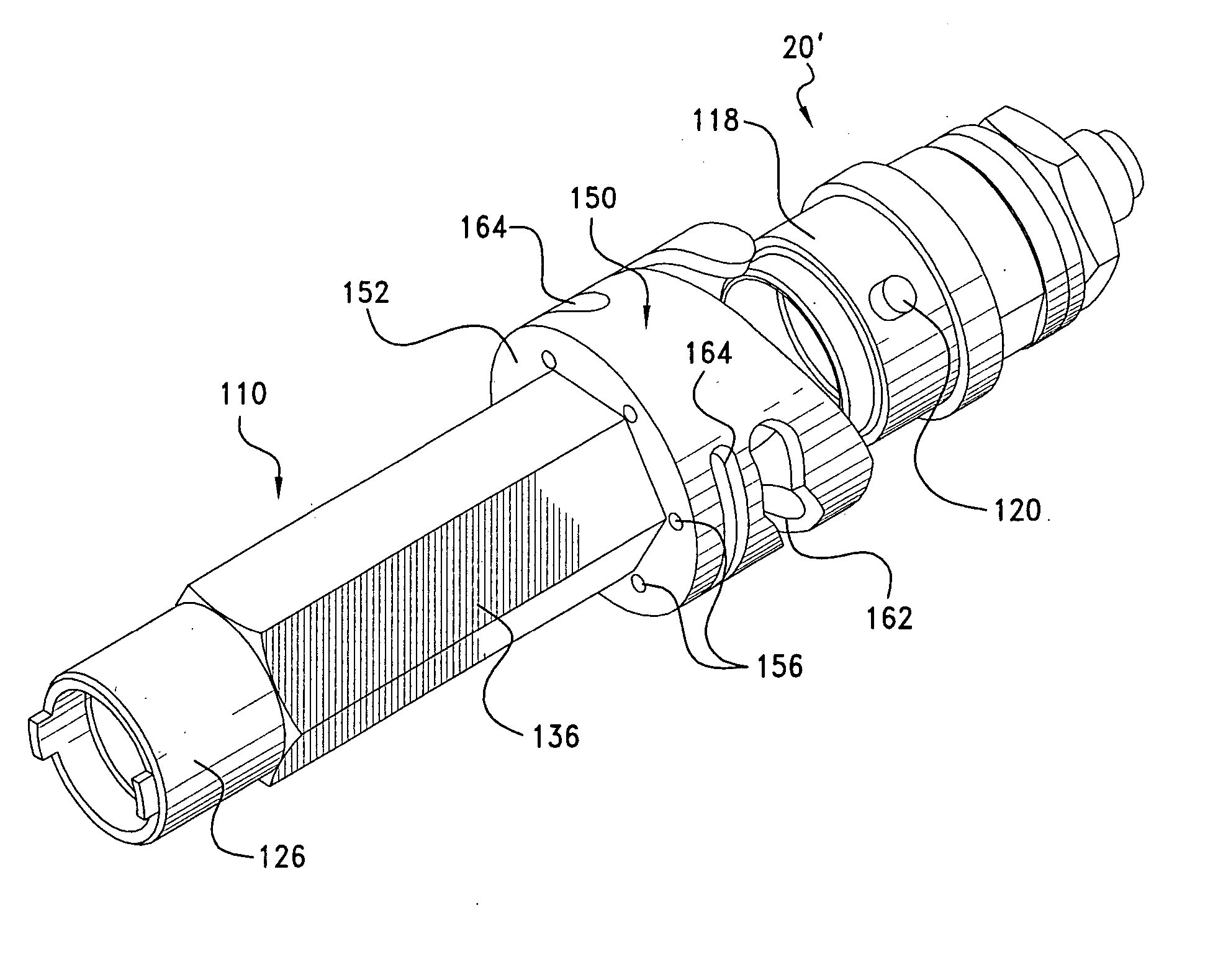
[0050] Continuing now with FIGS. 5-8, illustrated therein is the quick disconnect cryogenic coupler of the present invention, generally indicated at 20′. FIGS. 5 and 6 illustrate coupler 20′ and a nipple assembly 110 in the uncoupled position, whereas FIGS. 7 and 8 illustrate same in the coupled position. Coupler 20′ is similar to coupler 20, with like parts being denominated with the same numeral and the addition of a prime (′) superscript as a suffix.

[0051] Specifically, coupler body 22′ together with cut bushing 30′ and seal member 86′ is substantially similar to coupler body 22, bushing 30 and seal member 86. Adaptor 24′ differs from adaptor 24 only by the addition, to intermediate portion 66′, of an exterior threaded portion 114 and a complementary nut member 116. Coupler sleeve 26′ differs from coupler sleeve 26 mainly in that coupler 26′ has a generally tubular outer peripheral surface 122 that includes a recessed diameter frontal portion 118 that is provided with at least on...


PUM


Abstract

A generally cylindrical quick disconnect female cryogenic coupler, interconnected with a cryogenic fluid transfer apparatus, includes a coupler body with a first cavity housing a laterally severed tubular bushing, an adaptor having one end attached to the coupler body and another end to the apparatus, a normally closed-biased valve between the coupler body and the adaptor, a coupling sleeve, attached to the coupler body having, a frusto-conical inlet portion, and a vent fitting having one end connected with a coupling sleeve radial aperture and another end in operative connection with a cryogenic fluid storage vessel, associated with the noted apparatus, to permit the inlet purging by using the vessel's own gaseous phase as a purging medium during liquid fluid transfer operation. The severed bushing inhibits ice formation, at an inlet/male nipple interface during the noted transfer. A method for purging moisture at the noted interface is also set forth.

Description

CROSS-REFERENCE TO RELATED CASE [0001] The present application claims the benefits of the filing date of U.S. Provisional Application No. 60 / 591,288, filed Jul. 27, 2004.BACKGROUND OF THE INVENTION [0002] 1. Field of the Invention [0003] The present invention pertains to quick disconnect couplers operatively inter-connected with a cryogenic liquid fluid transfer apparatus and associated with a cryogenic fluid storage vessel. Specifically, the invention pertains to the use of a laterally severed tubular bushing that serves to inhibit ice formation, at a coupler inlet / male nipple interface during liquid fluid transfer. In addition, a vent fitting, having one end attached to radial aperture in a coupling sleeve inlet portion, and another end in operative connection with the cryogenic storage vessel, permits inlet purging by using the vessel's own gaseous phase as a purging medium during the liquid fluid transfer operation. [0004] Quick disconnect couplers are well known and are utilize...

Claims


Application Information

Patent Timeline
IPC IPC(8): F16L17/00
CPCA61M16/08F16L37/40F16L37/32A61M16/0816Y10S285/904A61M2202/0208A61M2202/03Y10T137/87949Y10T137/87957A61M2202/0007
Inventor LAMBERT, TODD DENNISELLIS, SHAWN DAVIDCALVO, MARIO ALEJANDRO
Owner PARKER HANNIFIN CORP
Why Eureka
Try Eureka