Distributed power generation, conversion, and storage system

a technology of distribution and power generation, applied in the direction of electric vehicles, transportation and packaging, emergency power supply arrangements, etc., can solve the problems of insufficient electric power, surges, dips or other disruptions, voltage transients, etc., and achieve the effect of reducing the need for stored power and ensuring reliability

Inactive Publication Date: 2006-02-02
BRYDE JAN HENRIK +1
View PDF10 Cites 21 Cited by
  • Summary
  • Abstract
  • Description
  • Claims
  • Application Information

AI Technical Summary

Benefits of technology

[0011] The present invention is directed to a distributed power generating system that enables very rapid and reliable start-up of the engine used to generate back-up power, thereby substantially reducing the need for stored power.

Problems solved by technology

Due to the high cost of building and operating electric power generating plants and their associated power grid, most electrical power is produced by large electric utilities that control distribution for defined geographical areas.
Electric power distributed in the traditional, centralized manner tends to experience undesirable frequency variations, voltage transients, surges, dips or other disruptions due to changing load conditions, faulty or aging equipment, and other environmental factors.
This electric power is inadequate for many customers that require a premium source of power (high quality) due to the sensitivity of their equipment (e.g., computing or telecommunications providers) or that require high reliability without disruption (e.g., hospitals).
The utilities that traditionally operate centralized power generating plants are increasingly reluctant to make the large investments in modernized facilities and distribution equipment needed to improve the quality and reliability of their electric power due to regulatory, environmental, and political considerations.
Notwithstanding these and other advantages of distributed power generation, there are other disadvantages that must be overcome to achieve wider acceptance of the technology.
Distributed power generating systems that utilize an engine to drive a generator tend to be slow to achieve an operational speed from start up, and consequently are slow to provide a source of back-up power.
Battery storage systems are large, expensive, heavy, and have relatively short life expectancy.

Method used


Image

  • Distributed power generation, conversion, and storage system
  • Distributed power generation, conversion, and storage system
  • Distributed power generation, conversion, and storage system

Examples


Embodiment Construction

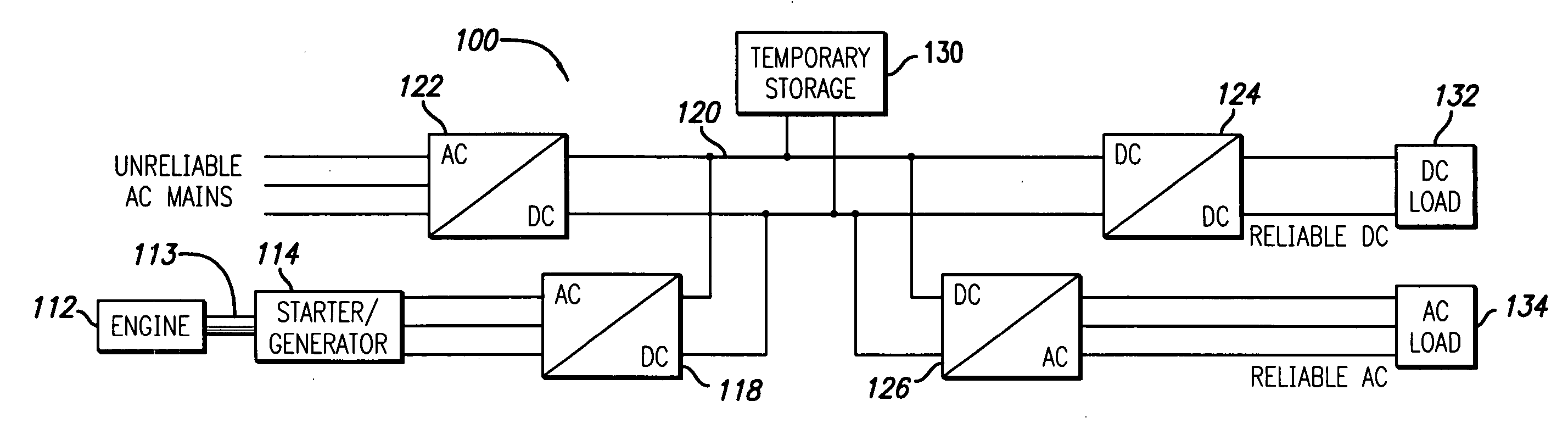
[0022] The present invention satisfies the need for a distributed power generating system to serve as an alternative to or enhancement of centralized power generation. Specifically, the present invention provides a distributed power generating system that achieves an operational state very rapidly so as to reduce the reliance on stored power. In the detailed description that follows, like element numerals are used to describe like elements illustrated in one or more of the figures.

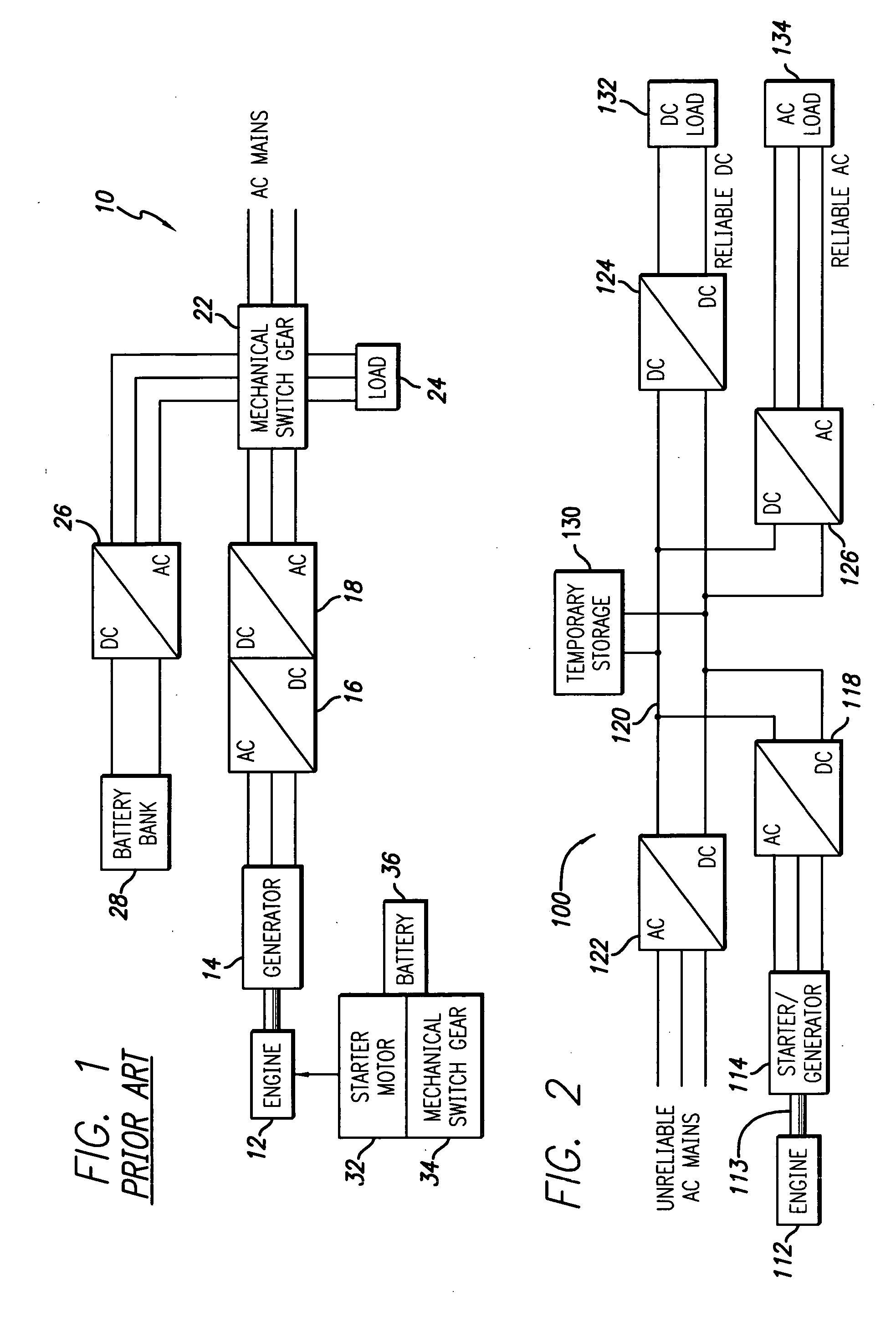
[0023]FIG. 1 illustrates a block diagram of a conventional distributed power generating system 10. The distributed power generating system 10 includes switchgear 22 that enables the coupling of AC power to a load 24 from a variety of sources. Under normal conditions, AC power is delivered to the load 24 through the switchgear 22 from the AC power mains connected to the commercial power grid. In the event of a fault of the AC mains, the switchgear 22 cuts off the AC mains and delivers AC power to the load ...


PUM


Abstract

A distributed power generating system enables very rapid and reliable start-up of an engine used to generate back-up power, thereby substantially reducing the need for stored power. More particularly, the distributed power generating system comprises a power bus electrically coupled to commercial power and to a load, an engine comprising a rotatable shaft, a starter/generator operatively coupled to the shaft of the engine and electrically coupled to the power bus, and a temporary storage device electrically coupled to the power bus. The starter/generator is adapted to start the engine from a standstill condition and rapidly bring the engine to an operational speed sustainable by the engine alone. In an embodiment of the invention, the distributed power generating system further comprises switchgear electrically coupled to the power bus, the starter/generator and the load. The switchgear selectively enables delivery of electrical power to the load from the starter/generator without passing through the power bus, delivery of electrical power from the temporary storage device to the starter/generator through the power bus, and/or delivery of electrical power from the power bus to the load. In another embodiment of the invention, the distributed power generating system further comprises second switchgear electrically coupled to the commercial power, the starter/generator and the power bus. The second switchgear selectively enables at least one of delivery of electrical power to the starter/generator from the commercial power without passing through the power bus, delivery of electrical power from the commercial power to the power bus, and delivery of electrical power from the starter/generator to the power bus.

Description

RELATED APPLICATION DATA [0001] This is a continuation-in-part of co-pending patent application Ser. No. 10 / 361,400, for DISTRIBUTED POWER GENERATION, CONVERSION, AND STORAGE SYSTEM, filed Feb. 10, 2003.BACKGROUND OF THE INVENTION [0002] 1. Field of the Invention [0003] The present invention pertains to the generation of electrical power. In particular, this invention relates to distributed power generation systems for use close to where electricity is used (e.g., a home or business) to provide an alternative to or an enhancement of the traditional electric power system. [0004] 2. Description of Related Art [0005] Centralized electric power generating plants provide the primary source of electric power supply for most commercial, agricultural and residential customers throughout the world. These centralized power-generating plants typically utilize an electrical generator to produce electrical power. The generator has an armature that is driven by conversion of an energy source to k...

Claims


Application Information

Patent Timeline
Patent Type & Authority Applications(United States)
IPC IPC(8): H02J9/00H02J9/06H02J9/08
CPCH02J9/061H02J9/08H02J9/062
Inventor BRYDE, JAN HENRIKTHAKER, MAHESH NATVERLAL
Owner BRYDE JAN HENRIK
Why Eureka
Try Eureka