Fuel control system and method for distributed power generation, conversion, and storage system

a technology of power generation and control system, applied in the direction of engine starters, emergency power supply arrangements, electric control, etc., can solve the problems of insufficient electric power, surges, dips or other disruptions, voltage transients, etc., and achieve the effect of promoting rapid engine start-up, reducing the need for stored power, and ensuring reliability

Inactive Publication Date: 2005-08-02
POWER ONE INC
View PDF3 Cites 20 Cited by
  • Summary
  • Abstract
  • Description
  • Claims
  • Application Information

AI Technical Summary

Benefits of technology

[0011]The present invention is directed to a fuel delivery system for a distributed power generating system that enables very rapid and reliable start-up of the engine used to generate back-up power, thereby substantially reducing the need for stored power. The fuel delivery system rapidly delivers fuel to the engine in order to promote rapid start of the engine.
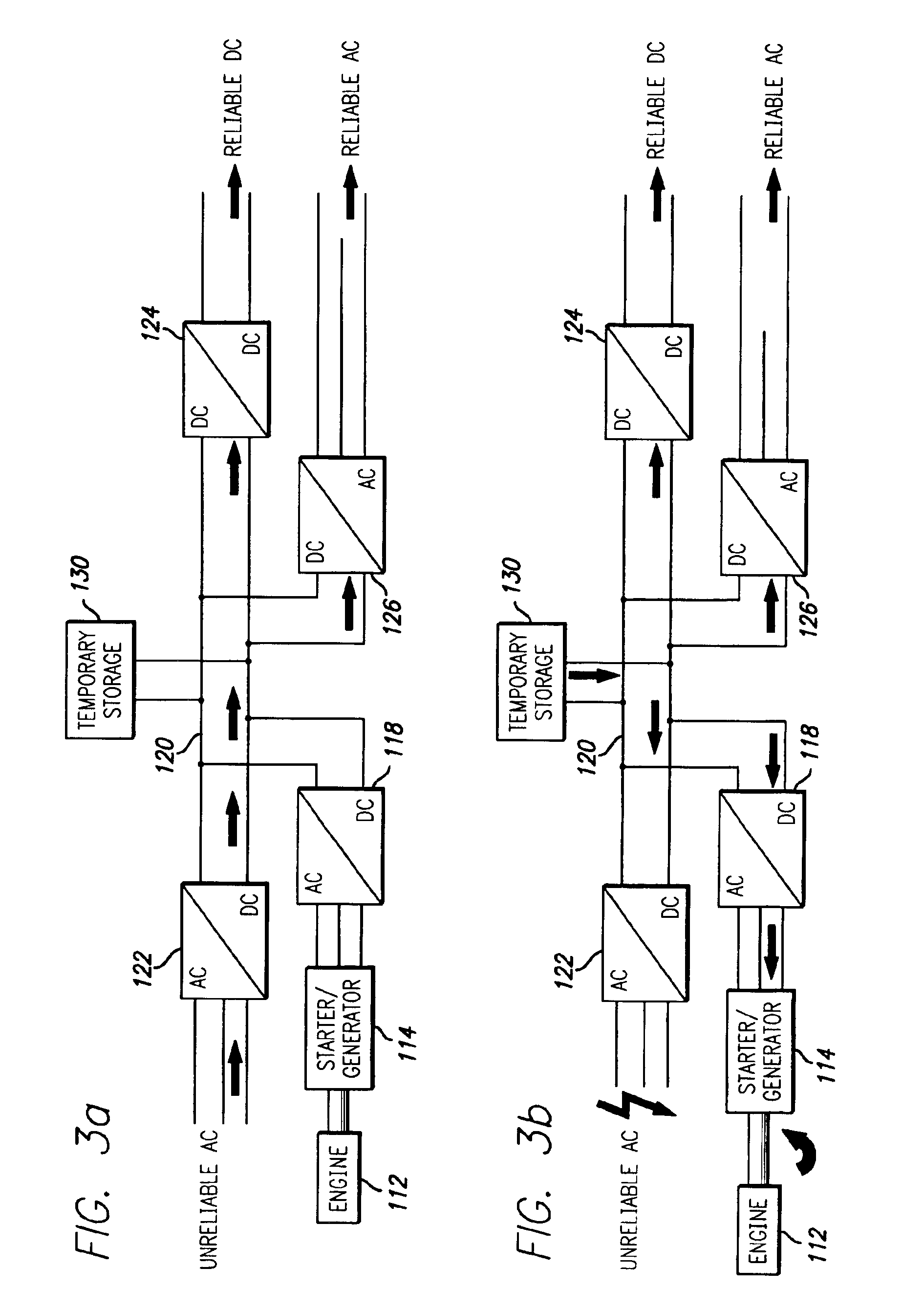
[0012]The distributed power generating system comprises a power bus electrically coupled to commercial power and to a load, an engine comprising a rotatable shaft, a starter / generator operatively coupled to the shaft of the engine and electrically coupled to the power bus, and a temporary storage device electrically coupled to the power bus. The starter / generator is adapted to start the engine from a standstill condition and rapidly brings the engine to an operational speed sustainable by the engine alone. To accomplish this, the starter / generator has a short time torque capability higher than the rated torque of the engine and starter / generator. When the engine reaches the operational speed, the starter / generator delivers electrical power to the power bus. Upon a fault of the commercial power, the temporary storage device supplies electrical power to the power bus for delivery to the load and for powering the starter / generator until the engine reaches the operational speed, whereupon the starter / generator takes over supply of electrical power to the power bus for delivery to the load. The temporary storage device may further comprise at least one capacitor that is charged by current on the power bus when the engine reaches the operational speed.
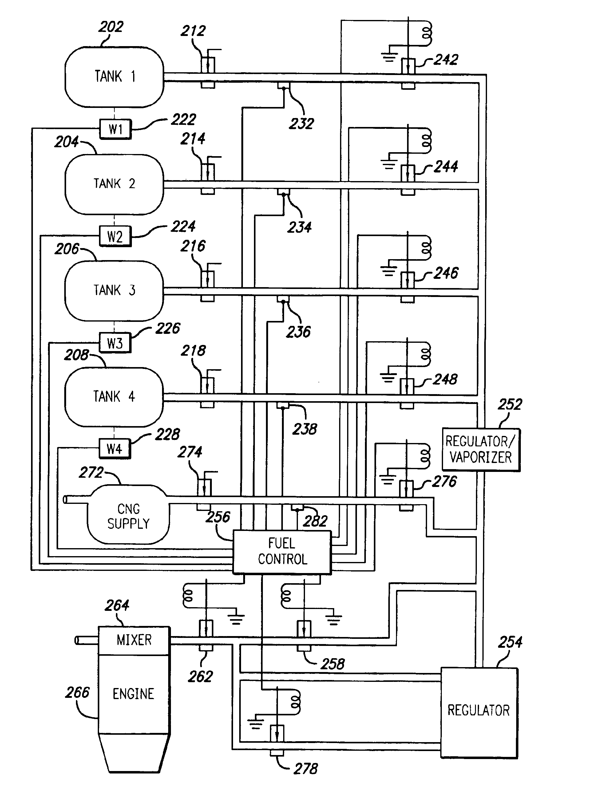
[0013]In an embodiment of the invention, the power generating system further includes a plurality of redundant fuel tanks each containing liquid fuel, such as propane, at a respective initial pressure level. A fuel delivery system operatively couples a selected one of the plurality of fuel tanks to the engine to supply fuel thereto. The fuel delivery system supplies vaporized fuel to the engine at a first reduced pressure level relative to the initial pressure level of the selected one of the plurality of fuel tanks while the starter / generator is starting the engine from the standstill condition, and supplies vaporized fuel to the engine at a second reduced pressure level lower than the first reduced pressure level when the engine reaches the operational speed. By supplying fuel to the engine at the first reduced pressure level, the fuel is delivered rapidly to the engine in order to promote fast startup from the standstill condition.
[0014]More specifically, a manually operative tank cutoff valve is coupled between each respective one of the plurality of fuel tanks and the fuel delivery system. An automatically operative main cutoff valve is disposed close to the engine so as to maintain a supply of vaporized fuel close to the engine and avoid the re-pressurization of the main fuel line upon subsequent start up of the engine. An automatically operative tank cutoff valve is disposed upstream from each respective one of the plurality of fuel tanks. A first regulator reduces the fuel pressure from the selected one of the plurality of fuel tanks to the first reduced pressure level. A second regulator reduces the fuel pressure from the first reduced pressure level to the second reduced pressure level. A bypass valve couples the first regulator directly to the engine and is selectively activated while the starter / generator is starting the engine from the standstill condition. In a further embodiment of the invention, a secondary fuel source is coupled to the fuel delivery system for supply of a secondary fuel to the engine, such as compressed natural gas.

Problems solved by technology

Due to the high cost of building and operating electric power generating plants and their associated power grid, most electrical power is produced by large electric utilities that control distribution for defined geographical areas.
Electric power distributed in the traditional, centralized manner tends to experience undesirable frequency variations, voltage transients, surges, dips or other disruptions due to changing load conditions, faulty or aging equipment, and other environmental factors.
This electric power is inadequate for many customers that require a premium source of power (high quality) due to the sensitivity of their equipment (e.g., computing or telecommunications providers) or that require high reliability without disruption (e.g., hospitals).
The utilities that traditionally operate centralized power generating plants are increasingly reluctant to make the large investments in modernized facilities and distribution equipment needed to improve the quality and reliability of their electric power due to regulatory, environmental, and political considerations.
Notwithstanding these and other advantages of distributed power generation, there are other disadvantages that must be overcome to achieve wider acceptance of the technology.
Distributed power generating systems that utilize an engine to drive a generator tend to be slow to achieve an operational speed from start up, and consequently are slow to provide a source of back-up power.
Battery storage systems are large, expensive, heavy, and have relatively short life expectancy.

Method used


Image

  • Fuel control system and method for distributed power generation, conversion, and storage system
  • Fuel control system and method for distributed power generation, conversion, and storage system
  • Fuel control system and method for distributed power generation, conversion, and storage system

Examples


Embodiment Construction

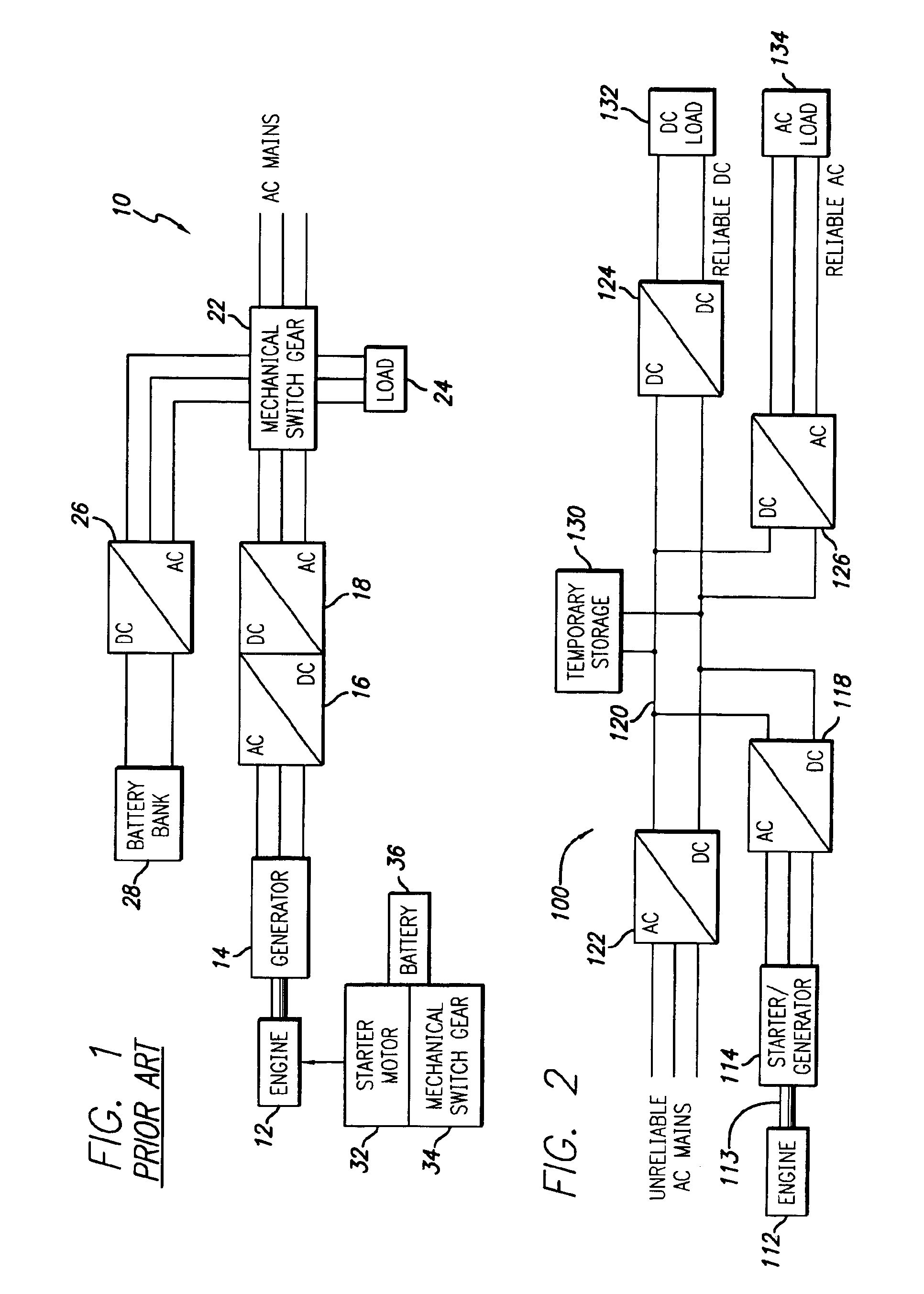
[0025]The present invention satisfies the need for a distributed power generating system to serve as an alternative to or enhancement of centralized power generation. Specifically, the present invention provides a distributed power generating system that achieves an operational state very rapidly so as to reduce the reliance on stored power. According to a particular embodiment of the invention, a fuel control system is provided that quickly delivers fuel to the combustion engine used to generate power, to thereby facilitate fast achievement of the desired operational state. In the detailed description that follows, like element numerals are used to describe like elements illustrated in one or more of the figures.

[0026]FIG. 1 illustrates a block diagram of a conventional distributed power generating system 10. The distributed power generating system 10 includes switchgear 22 that enables the coupling of AC power to a load 24 from a variety of sources. Under normal conditions, AC pow...


PUM


Abstract

A distributed power generating system enables very rapid and reliable start-up of an engine used to generate back-up power, thereby substantially reducing the need for stored power. More particularly, the distributed power generating system comprises a power bus electrically coupled to commercial power and to a load, an engine comprising a rotatable shaft, a starter / generator operatively coupled to the shaft of the engine and electrically coupled to the power bus, and a temporary storage device electrically coupled to the power bus. The starter / generator is adapted to start the engine from a standstill condition and rapidly bring the engine to an operational speed sustainable by the engine alone. In an embodiment of the invention, the power generating system further includes a plurality of redundant fuel tanks each containing liquid fuel, such as propane, at a respective initial pressure level. A fuel delivery system operatively couples a selected one of the plurality of fuel tanks to the engine to supply fuel thereto. The fuel delivery system supplies vaporized fuel to the engine at a first reduced pressure level relative to the initial pressure level of the selected one of the plurality of fuel tanks while the starter / generator is starting the engine from the standstill condition, and supplies vaporized fuel to the engine at a second reduced pressure level lower than the first reduced pressure level when the engine reaches the operational speed. By supplying fuel to the engine at the first reduced pressure level, the fuel is delivered rapidly to the engine in order to promote fast startup from the standstill condition.

Description

RELATED APPLICATION DATA[0001]This is a continuation-in-part of copending patent application Ser. No. 10 / 361,400, for DISTRIBUTED POWER GENERATION, CONVERSION, AND STORAGE SYSTEM, filed Feb. 10, 2003.BACKGROUND OF THE INVENTION[0002]1. Field of the Invention[0003]The present invention pertains to the generation of electrical power. In particular, this invention relates to distributed power generation systems for use close to where electricity is used (e.g., a home or business) to provide an alternative to or an enhancement of the traditional electric power system.[0004]2. Description of Related Art[0005]Centralized electric power generating plants provide the primary source of electric power supply for most commercial, agricultural and residential customers throughout the world. These centralized power-generating plants typically utilize an electrical generator to produce electrical power. The generator has an armature that is driven by conversion of an energy source to kinetic ener...

Claims


Application Information

Patent Timeline
Patent Type & Authority Patents(United States)
IPC IPC(8): H02J9/06H02J9/08F02D19/06F02D29/06
CPCF02D19/0647F02D29/06F02M21/0212F02M21/0224H02J9/061H02J9/08F02D19/0681F02D19/0665H02J9/062Y02T10/36Y02T10/32Y02T10/30
Inventor BRYDE, JAN HENRIK
Owner POWER ONE INC
Why Eureka
Try Eureka