Apparatus and method for evaluating magnetic heads, and disk for use in evaluating magnetic heads

a magnetic head and apparatus technology, applied in the field of apparatus and methods for evaluating magnetic heads, can solve the problems of abnormal waveform on the output of the gmr element, no resistance change nor shape change, and the head element is inevitably very weak to esd

Inactive Publication Date: 2006-02-02
TOSHIBA STORAGE DEVICE CORP
View PDF9 Cites 7 Cited by
  • Summary
  • Abstract
  • Description
  • Claims
  • Application Information

AI Technical Summary

Benefits of technology

[0021] As described above in detail, the present invention can provide a method of evaluating a magnetic head, which scarcely damages the element part of the magnetic head. Although the method is very simple, the method can prevent the fixed layer of the GMR element from undergoing inversion of magnetization direction after the magnetic head is incorporated into a magnetic disk drive. Thus, any magnetic disk drive that has a magnetic head evaluated by this method as a good one can be very reliable, scarcely causing field damages.

Problems solved by technology

The head element is inevitably very weak to ESD due to static electricity.
The magnetic breakdown results in neither resistance change nor shape change, but causes an abnormal waveform on the output of the GMR element.
For example, the magnetic breakdown makes the reproduced waveform unstable or changes the amplitudes of the positive and negative halves of the waveform reproduced.
If this magnetic breakdown occurs, the magnetic head cannot correctly detect the data.
This causes errors in the data or makes it impossible to reproduce the servo signals.
Then, the magnetic head can no longer be accurately positioned.
Consequently, the data signals or the servo signals that the head has reproduced are erroneous.
This is probably because the magnetic head has ESD not so prominent to cause waveform inversion and therefore passes the first test, and is incorporated into a magnetic disk drive, but receives a small impact due to, for example, contamination, inevitably generating a inverse magnetic field and hence inverting the direction of magnetization of the GMR element.

Method used


Image

  • Apparatus and method for evaluating magnetic heads, and disk for use in evaluating magnetic heads
  • Apparatus and method for evaluating magnetic heads, and disk for use in evaluating magnetic heads
  • Apparatus and method for evaluating magnetic heads, and disk for use in evaluating magnetic heads

Examples


Embodiment Construction

[0030] Hereinafter, embodiments of the present invention will be described, with reference to the accompanying drawings.

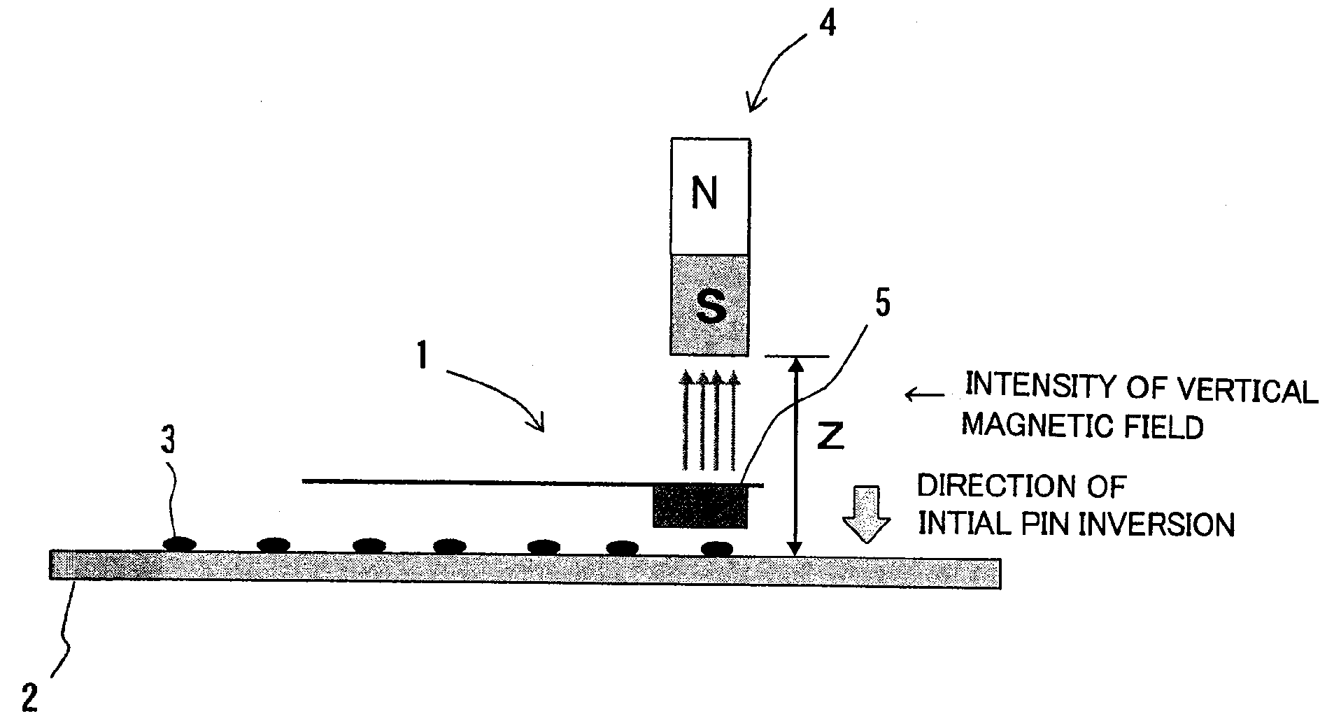
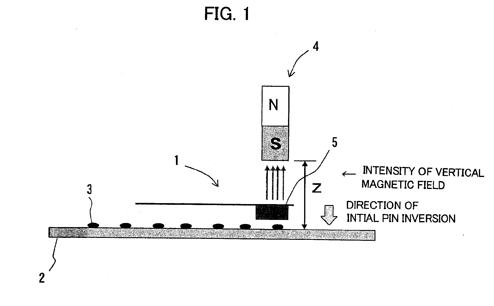
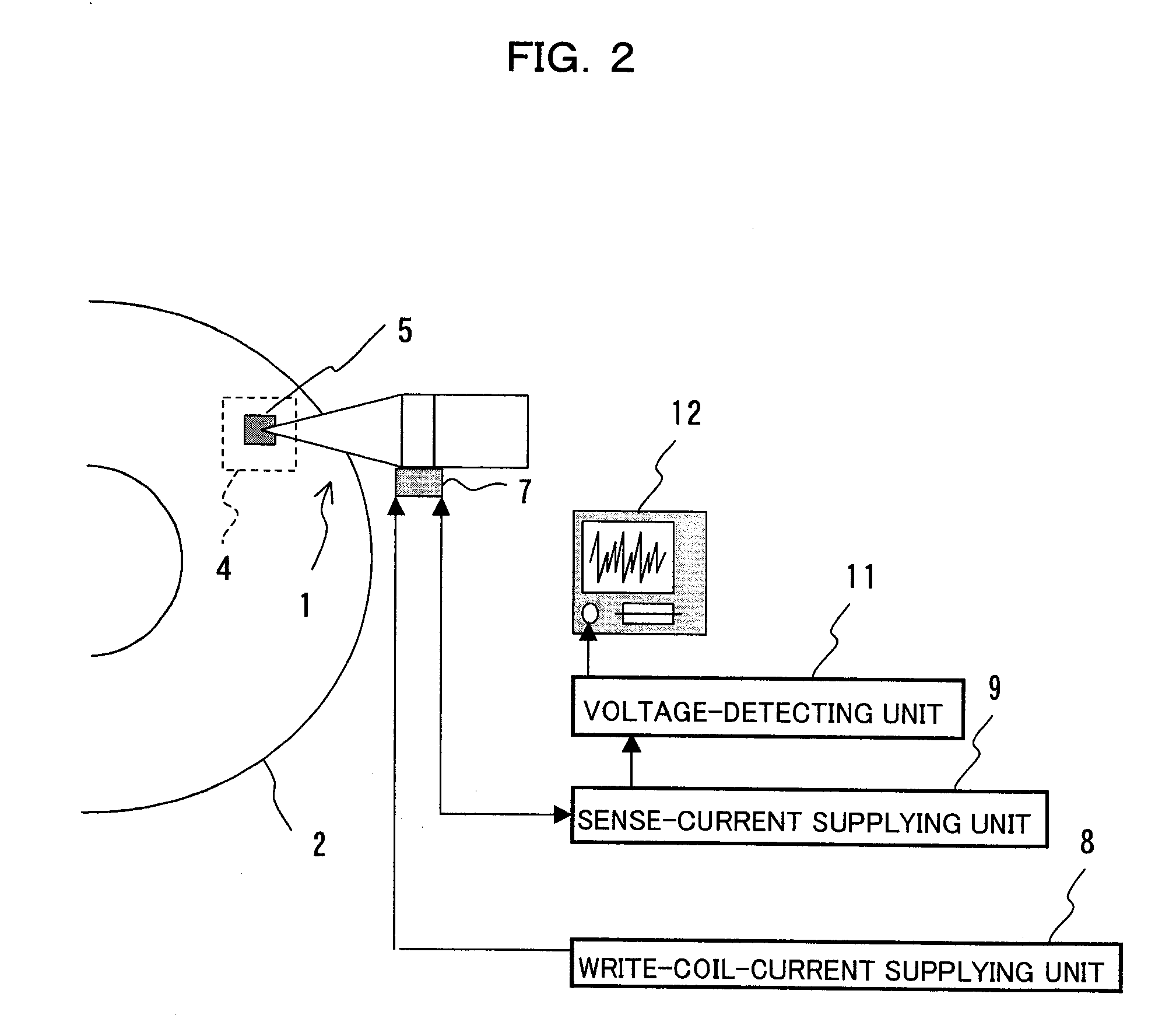
[0031]FIG. 1 is a diagram illustrating a method of evaluating magnetic heads, according to an embodiment of the invention. FIG. 2 is a block diagram of an apparatus for evaluating magnetic heads, according to another embodiment of this invention. FIG. 3 is a plan view depicting a disk that is used in the present embodiment. FIG. 4 is a perspective view of one of the laser bump used in the present embodiment. FIG. 5 is a diagram explaining an algorithm of the method of evaluating magnetic heads, according to this embodiment. FIGS. 6A and 6B are diagrams representing the PIN inversion observed at the laser bump shown in FIG. 4.

[0032] The method of evaluating magnetic heads, according to this embodiment, is designed to determine as to whether the fixed layer of a GMR head 1 undergoes the inversion of magnetization direction (i.e., PIN inversion). In the method, as s...


PUM


Abstract

A DC current is supplied to the write coil of a GMR head 1 equipped with a completed HGA (Head Gimbal Assembly). The element part of the GMR head 1 is thereby thermally deformed. Thus deformed, the element part protrudes, abutting on a rotating laser-bump disk 2 that, above which the HGA is floating. When the element part abuts on the disk 2, a magnetic field (2470 gauss) that extends in a direction opposite to the magnetization direction of the fixed layer of the GMR head 1 is applied to the top of a core slider 5.

Description

BACKGROUND OF THE INVENTION [0001] 1. Field of the Invention [0002] The present invention relates to an apparatus and method for evaluating magnetic heads. More particularly, the invention relates to a technique of evaluating GMR heads before they are incorporated into magnetic disk drives. The invention relates to an apparatus, a method and a disk that can evaluate GMR heads that cause no magnetic inversion at the GMG-head supporting layer of a magnetic disk drive after a GMR head is incorporated into the magnetic disk drive. [0003] 2. Description of the Related Art [0004] In recent years, magnetic disk drives have become smaller and acquired a larger storage capacity. It is therefore increasingly demanded that the magnetic disk drives should magnetically reproduce data from disks at higher sensitivity. Developed recently as a magnetic head with use of a magnetoresistive effect is the GMR head (also known as spin-valve head). [0005] The head element of the GMR head has a spin-valve...

Claims


Application Information

Patent Timeline
Patent Type & Authority Applications(United States)
IPC IPC(8): G01R33/12
CPCG11B5/3903G11B5/4555G11B5/455
Inventor YAMAMOTO, KENROU
Owner TOSHIBA STORAGE DEVICE CORP
Why Eureka
Try Eureka