Liquid crystal display device having thin polarizing film and thin phase retardation film

a technology of polarizing film and phase retardation film, which is applied in the direction of optics, instruments, electrical equipment, etc., can solve the problems of limited viewing distance, inability to view 3d images clearly, limited viewing angle, etc., and achieve the effect of reducing the fabrication process and reducing the fabrication cos

Inactive Publication Date: 2006-02-02
PAVONINE
View PDF13 Cites 41 Cited by
  • Summary
  • Abstract
  • Description
  • Claims
  • Application Information

AI Technical Summary

Benefits of technology

[0022] In the sixth embodiment of the present invention, the polarizing region is formed of a conductive metal differently from the structure of the fourth embodiment of the present invention. In this embodiment, since the polarizing film function and the electrode function are concurrently provided, two transparent electrodes and two insulation layers are not needed before and after the liquid crystal layer differently from the fourth embodiment of the present invention. Therefore, the fabrication process of the LCD device can be decreased, and the fabrication cost is also decreased.

Problems solved by technology

When a user wears polarizing glasses 25 and sees a 3D image, a viewing angle is limited, and a viewing distance is limited.
Since the 3D viewing angle is generally less than 16°, it is impossible to view 3D images clearly.

Method used


Image

  • Liquid crystal display device having thin polarizing film and thin phase retardation film
  • Liquid crystal display device having thin polarizing film and thin phase retardation film
  • Liquid crystal display device having thin polarizing film and thin phase retardation film

Examples


first embodiment

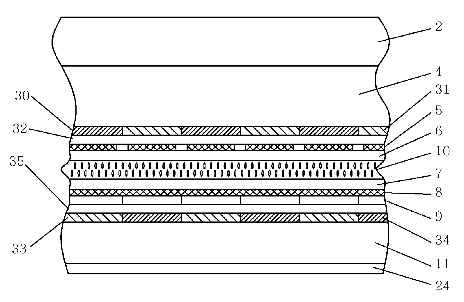
[0043] The 2D and 3D LCD device according to a first embodiment of the present invention will be described with reference to FIGS. 3 and 4. Polarizing regions are given reference numerals of 30, 31, 33, 34, 60, 61, 80 and 81 in order to recognize the regions from a polarizing film because the polarizing directions are orthogonal at 90° in a lattice shape on one plane.

[0044] As shown in FIGS. 3 and 4, in the liquid crystal device capable of displaying a 2D image and a 3D image according to the first embodiment of the present invention, a first polarizing region 30 having a polarizing direction of 0° or 45° formed on a plane of the first transparent substrate aligned on a front surface of the backlight unit 2 and a second polarizing region 31 that has a polarizing direction of 90° or 135° are aligned in an orthogonal structure. A first insulation layer 32 is aligned at a front surface of the first polarizing region 30 and the second polarizing region 31. A first transparent electrode...

second embodiment

[0053] The 2D and 3D liquid crystal display device according to the second embodiment of the present invention will be described. FIG. 6 is a view of the second embodiment, and FIG. 7 is a cross sectional view of FIG. 6.

[0054] As shown in FIG. 6, a part of the LCD device capable of displaying 2D and 3D images according to the second embodiment of the present invention is changed as compared with the first embodiment of the present invention. The above changes will be described in detail.

[0055] As shown in FIG. 6, in the LCD device capable of displaying 2D and 3D images according to the second embodiment of the present invention, a third polarizing film 52 formed of straight line polarizing films on its entire surface is disposed at the front surface of the backlight unit 2. The second 1 / 2 phase retardation film 50 and the transparent unit 51 are disposed at the front surface of the first transparent substrate 4 with a certain width and distance. Next, the first insulation layer 32...

third embodiment

[0061]FIG. 8 is a view of the third embodiment of the present invention, and FIG. 9 is a cross sectional view of FIG. 8. As shown in FIG. 8, the construction of the third embodiment of the present invention is similar with the second embodiment of the present invention except for a ¼ phase retardation film 68 that is additionally provided in this embodiment. In more detail, the light from the backlight unit 2 is changed to straight line polarizing light having 90° or 135° polarizing direction while transmitting the third polarizing film 52 formed of straight line polarizing films.

[0062] The light transmitted the transparent unit 51 disposed at the front surface of the first transparent substrate 4 is changed to straight line polarizing light having a 90° rotated polarizing direction while transmitting the liquid crystal layer 10. Thereafter, the light transmits the fourth polarizing region 34 having a 0° or 45° polarizing direction. Next, the polarized light transmits the ¼ phase r...


PUM

PropertyMeasurementUnit
3D viewing angleaaaaaaaaaa
orthogonal angleaaaaaaaaaa
angleaaaaaaaaaa

Abstract

A LCD device having a thin phase retardation film is disclosed, which is achieved using a thin film polarizing film formed by accurately processing a thin aluminum film, a polarizing film of a nano imprint lithography method that uses polymer, and a polarizing film and a liquid crystal material that form a polarizing nano material thin film by uniformly coating a polarizing nano material (TCF).

Description

BACKGROUND OF THE INVENTION [0001] 1. Field of the Invention [0002] The present invention relates to a LCD (Liquid Crystal Display) device having a thin polarizing film and a thin phase retardation film, and in particular to a LCD device having a thin polarizing film and a thin phase retardation film capable of displaying a 2D (dimension) image and a 3D (dimension) image. [0003] 2. Description of the Background Art [0004] The Korean patent gazette No. 2992-41382 (laid-open date: Jun. 1, 2002) entitled “Liquid crystal shutter for 3D display device” discloses a technique capable of removing Moire interference phenomenon fin a display device that is designed to implement a 3D based on a parallax barrier. [0005] The U.S. Pat. No. 6,122,103 of US Moxtek Inc. discloses a thin polarizing film manufactured using a thin aluminum film. [0006] The U.S. Pat. No. 6,813,077 of Corning Inc. discloses a technique of fabricating a thin film of a wire grid with an imprint method. In addition, the U.S...

Claims


Application Information

Patent Timeline
Patent Type & Authority Applications(United States)
IPC IPC(8): G02F1/1335G02B30/25H04N13/00
CPCG02B27/26H04N13/0452H04N13/0434G02F1/133528G02B30/25H04N13/337H04N13/356G02F1/1335
Inventor LEE, SUNG-JUNG
Owner PAVONINE
Why Eureka
Try Eureka