
Substrate mounted with electronic element thereon and liquid ejection head including the substrate

a technology of electronic elements and substrates, which is applied in the direction of electrical apparatus construction details, printing, inking apparatus, etc., can solve the problems of excessive rise of temperature of electronic elements, insufficient heat transmission from electronic elements to substrates, and inability to encourage heat radiation from the side of electronic elements contacting with substrates, etc., to achieve efficient radiation of heat generated by drivers and high thermal conductivity

Inactive Publication Date: 2006-02-02
BROTHER KOGYO KK
View PDF6 Cites 17 Cited by
  • Summary
  • Abstract
  • Description
  • Claims
  • Application Information

AI Technical Summary

Benefits of technology

[0007] An object of the present invention is to provide a substrate mounted thereon with an electronic element, which is capable of efficient radiation of heat generated by the electronic element, and also to provide a liquid ejection head including the substrate.
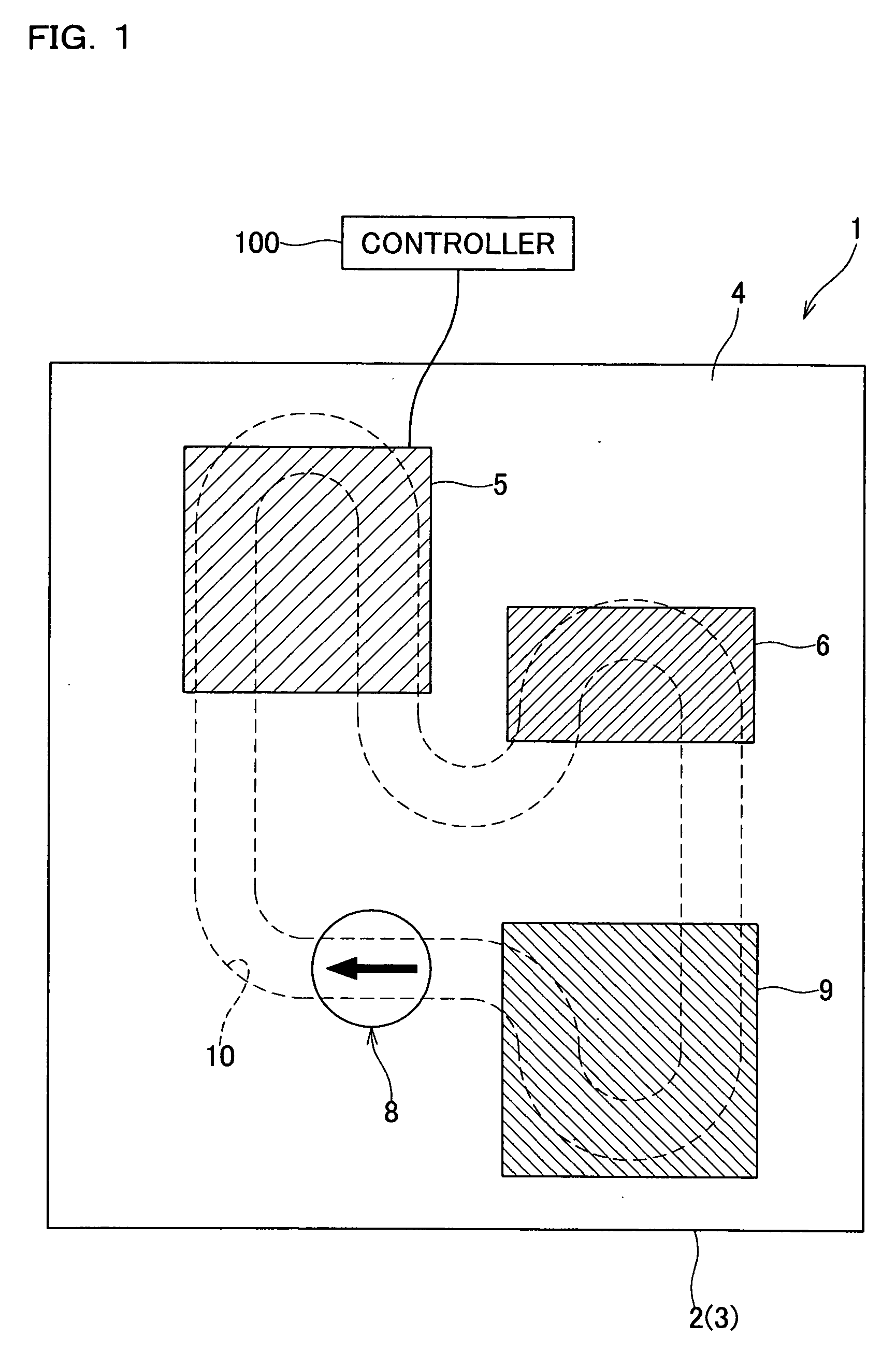
[0009] In the foregoing substrate mounted with an electronic element thereon, the metal base has a high thermal conductivity, and the ceramic insulator provided on the base also has a high thermal conductivity. The heat-generating electronic element is mounted on a side of the insulator opposite to a side thereof facing the base. Heat generated by the electronic element is transmitted via the insulator to the base, and further transmitted to the radiator by which the heat is radiated. Therefore, the heat generated by the electronic element can efficiently be radiated.
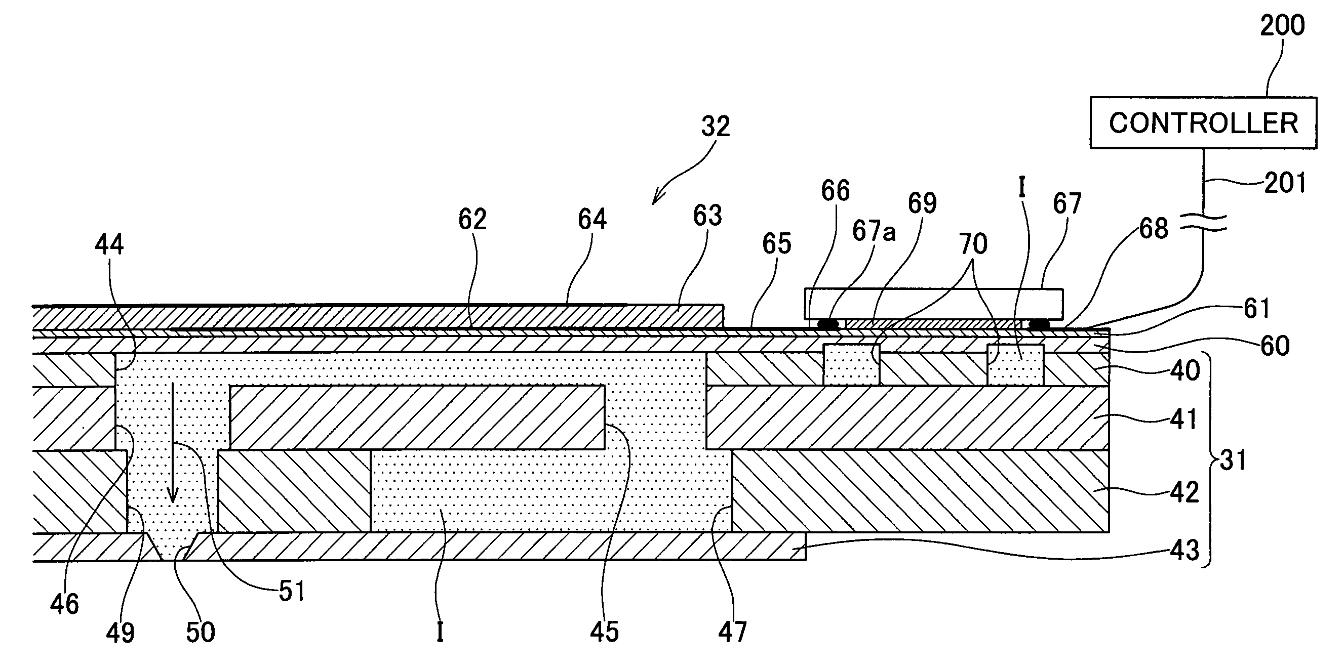
[0011] In the foregoing liquid ejection head, when the driver drives the actuator unit to change the volume of the pressure chamber, liquid within the pressure chamber receives pressure so that the liquid goes through the first fluid passage and is ejected from the nozzle. The metal diaphragm having a high thermal conductivity is provided thereon with the ceramic insulator having a high thermal conductivity, too. The driver is mounted on the side of the insulator opposite to a side facing the diaphragm. Heat generated by the driver is transmitted via the insulator to the diaphragm, and further transmitted through the metallic plates to the liquid within the second fluid passage. The liquid receiving the heat flows within the second fluid passage while transporting the heat away from the driver and thus radiating the heat. As a consequence, the heat generated by the driver can efficiently be radiated.

Problems solved by technology

In the electronic device disclosed in the aforementioned reference, however, heat radiation is encouraged from the surface of the electronic element opposite to a side thereof, i.e., opposite to a side contacting with the substrate, while heat radiation cannot be encouraged from the side of the electronic element contacting with the substrate.
Therefore, the heat transmitted from the electronic element to the substrate cannot be sufficiently radiated.
This can cause a problem of excessive rise of temperature of the electronic element.

Method used


Image

  • Substrate mounted with electronic element thereon and liquid ejection head including the substrate
  • Substrate mounted with electronic element thereon and liquid ejection head including the substrate
  • Substrate mounted with electronic element thereon and liquid ejection head including the substrate

Examples


first embodiment

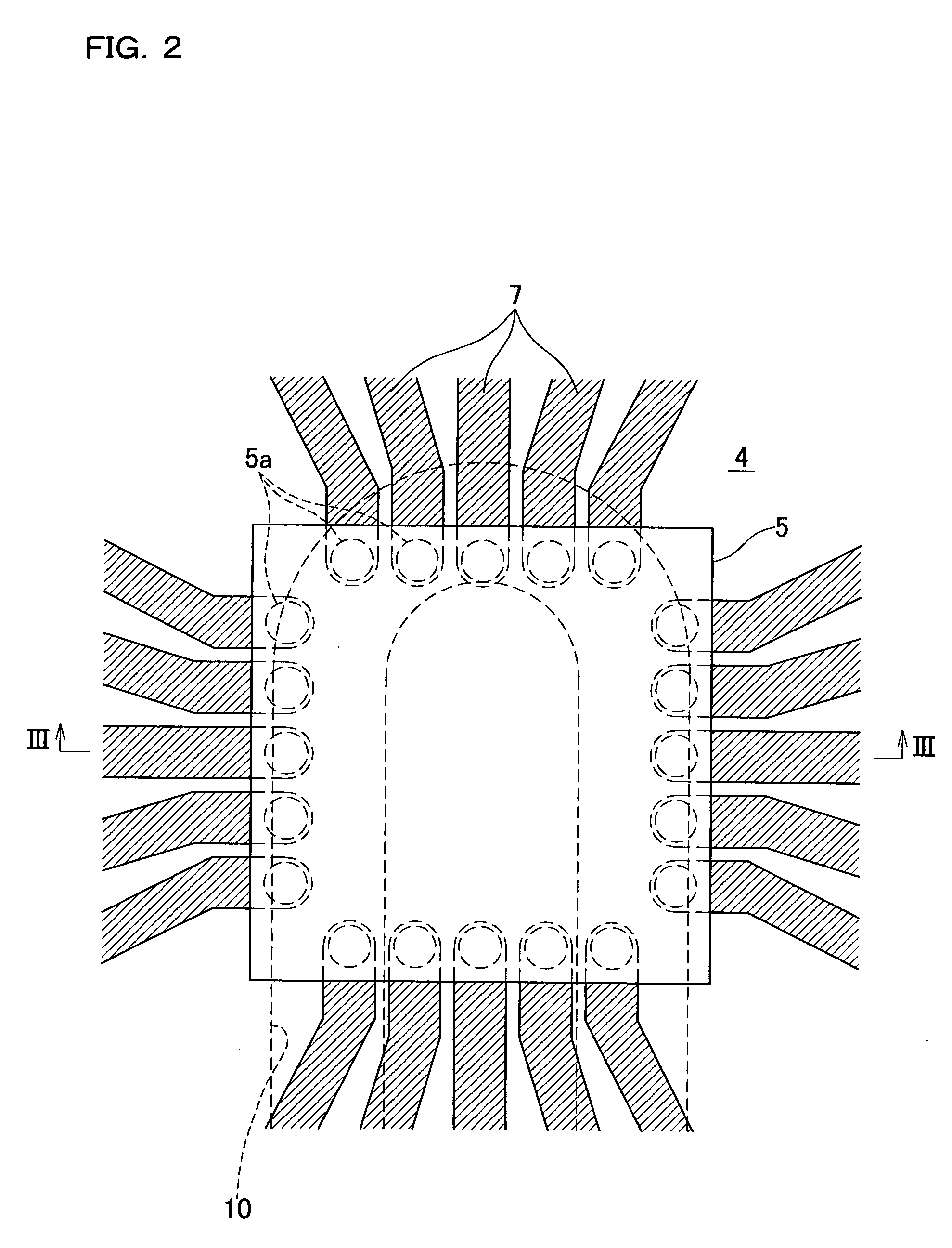
[0046] In the substrate 1 of the first embodiment described above, the plates 2 and 3 as the base are made of a metal having a high thermal conductivity, and the insulator 4 formed on the plate 2 is also made of a ceramic material having a high thermal conductivity. The ICs 5 and 6 which generate heat are mounted on the side of the insulator 4 opposite to the side facing the plate 2. The heat generated by the ICs 5 and 6 is transmitted via the insulator to the plate 2, and further transmitted to the water W within the passage 10. The water W which has received the heat is pressurized by the pressurizer 8 to thereby flow within the passage, while transporting the heat away from the ICs 5 and 6 and at the same time radiating the heat via the plates 2 and 3 to the outside. Moreover, the heat transported by the water W within the passage 10 is radiated through the radiation plate 9 to the outside. In this embodiment, thus, the heat generated by the ICs 5 and 6 can efficiently be radiate...

second embodiment

[0087] In the above-described ink-jet head 30 of the second embodiment, the diaphragm 60 made of a metal having a high thermal conductivity is provided thereon with the insulator 61 made of a ceramic material having a high thermal conductivity, too. The driver IC 67 is mounted on a side of the insulator 61 opposite to a side thereof facing the diaphragm 60. Most of heat generated by the driver IC 67 is transmitted via the insulator 61 to the diaphragm 60, and further transmitted through the metallic cavity plate 40 to the ink I within the ink passage 70. The ink I which has received the heat flows within the ink passage 70 while transporting the heat away from the driver IC 67 and thus radiating the heat. As a consequence, the heat generated by the driver IC 67 can efficiently be radiated, so that excessive rise in temperature of the driver IC 67.

[0088] When the ink passage 70 does not communicate with the individual ink passage 51 formed within the passage unit 31, an additional sy...


PUM


Abstract

A substrate mounted with an electronic element thereon comprises a metal base, a ceramic insulator, and a radiator. The insulator is provided on a first side of the base. The insulator has a heat-generating electronic element mounted on a side thereof opposite to a side thereof facing the first side of the base. The radiator has a radiation capability higher than both of a radiation capability of the insulator and a radiation capability of the base, and radiates heat transmitted from the electronic element via the insulator to the base.

Description

BACKGROUND OF THE INVENTION [0001] 1. Field of the Invention [0002] The present invention relates to a substrate mounted thereon with a heat-generating electronic element such as an IC, and also to a liquid ejection head including the substrate. [0003] 2. Description of Related Art [0004] An electronic device such as a portable phone, a personal computer, or the like includes many electronic elements such as an integrated circuit (IC), a resistance, a capacitor, etc. which are mounted on a substrate. When a heat-generating electronic element such as an IC is mounted, heat generated by the electronic element must surely be radiated to the outside in order to prevent damage to the electronic element itself and damage to other elements therearound. However, for the purpose of downsizing an electronic device, there is a growing tendency for many electronic elements to be disposed close to each other in a small region on the substrate. This makes it difficult to radiate heat generated by...

Claims


Application Information

Patent Timeline
IPC IPC(8): H05K7/08
CPCB41J2/14233H01L2224/16B41J2202/08H01L23/367H01L23/3735H01L23/3736H01L23/473H05K1/0203H05K1/0272H05K1/053H05K3/305H05K2201/064H05K2201/066H05K2201/10674B41J2002/14491
Inventor SUGAHARA, HIROTO
Owner BROTHER KOGYO KK
Learn More