
Optical disk device and track-on method thereof

a technology of optical disk and track, applied in the field of optical disk devices, can solve the problem of extra time for retry operations, and achieve the effect of improving reliability and being convenient for users to us

Inactive Publication Date: 2006-02-02
FUNAI ELECTRIC CO LTD
View PDF3 Cites 9 Cited by
  • Summary
  • Abstract
  • Description
  • Claims
  • Application Information

AI Technical Summary

Benefits of technology

[0012] It is an object of the present invention to provide an optical disk device of which the reliability can be improved and which is easy for the user to use.
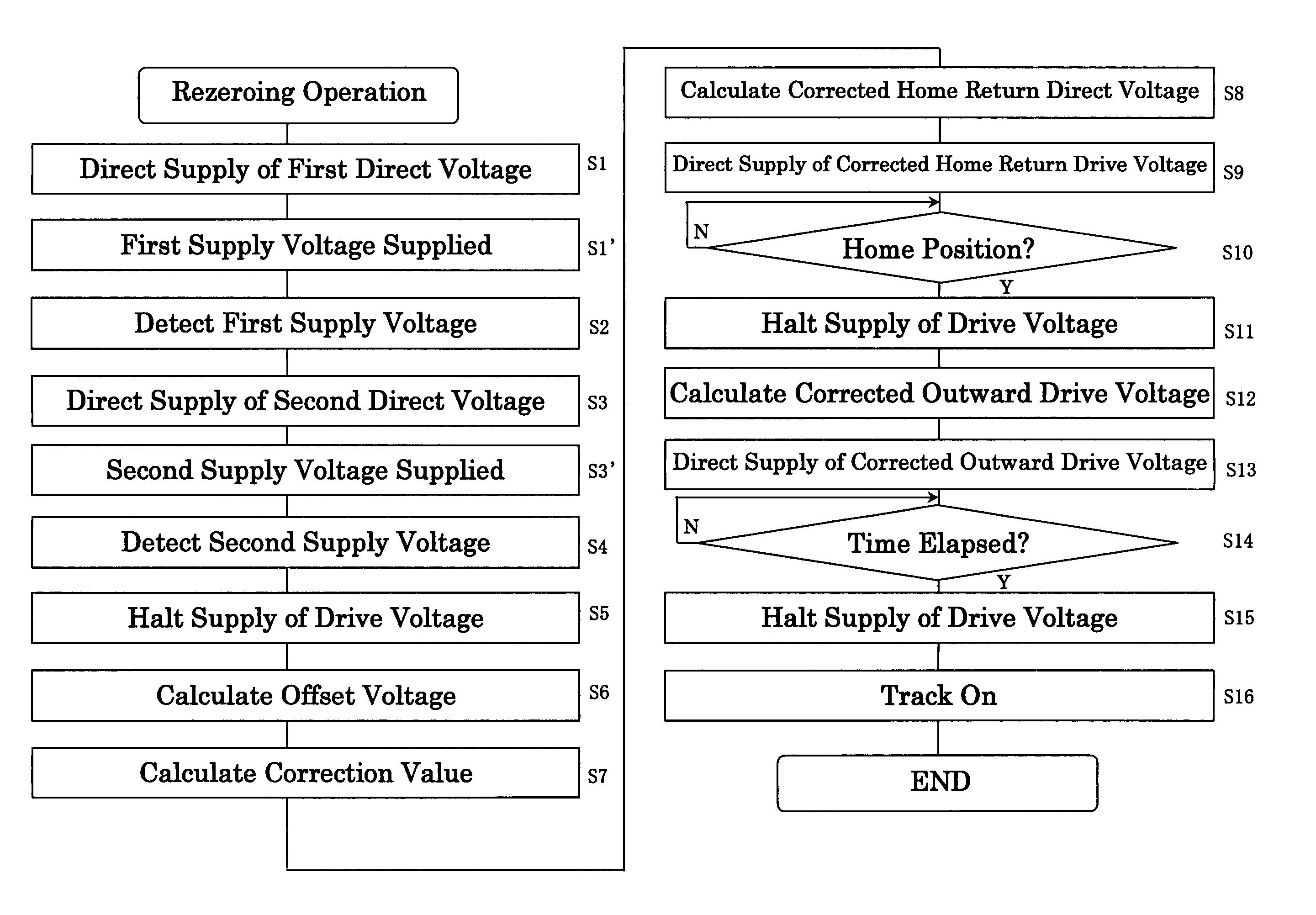
[0016] This means it is possible to suppress variance among optical disk devices in the drive voltage that is actually supplied to the thread motor in response to the directive from the drive controller to supply the drive voltage. As a result, there is less variance among optical disk devices in the track-on position of the optical disk (this position will hereinafter be referred to as the re-zeroing position). Accordingly, the reliability can be improved and the optical disk device is easy for the user to use.
[0019] With this constitution, the correction value is calculated when the power is turned on with an optical disk being mounted in the optical disk device, or when the optical disk is mounted in the optical disk device for the first time after the power is turned on. Therefore, the track-on position is less likely to be affected by changes in the re-zeroing position that occur over time.
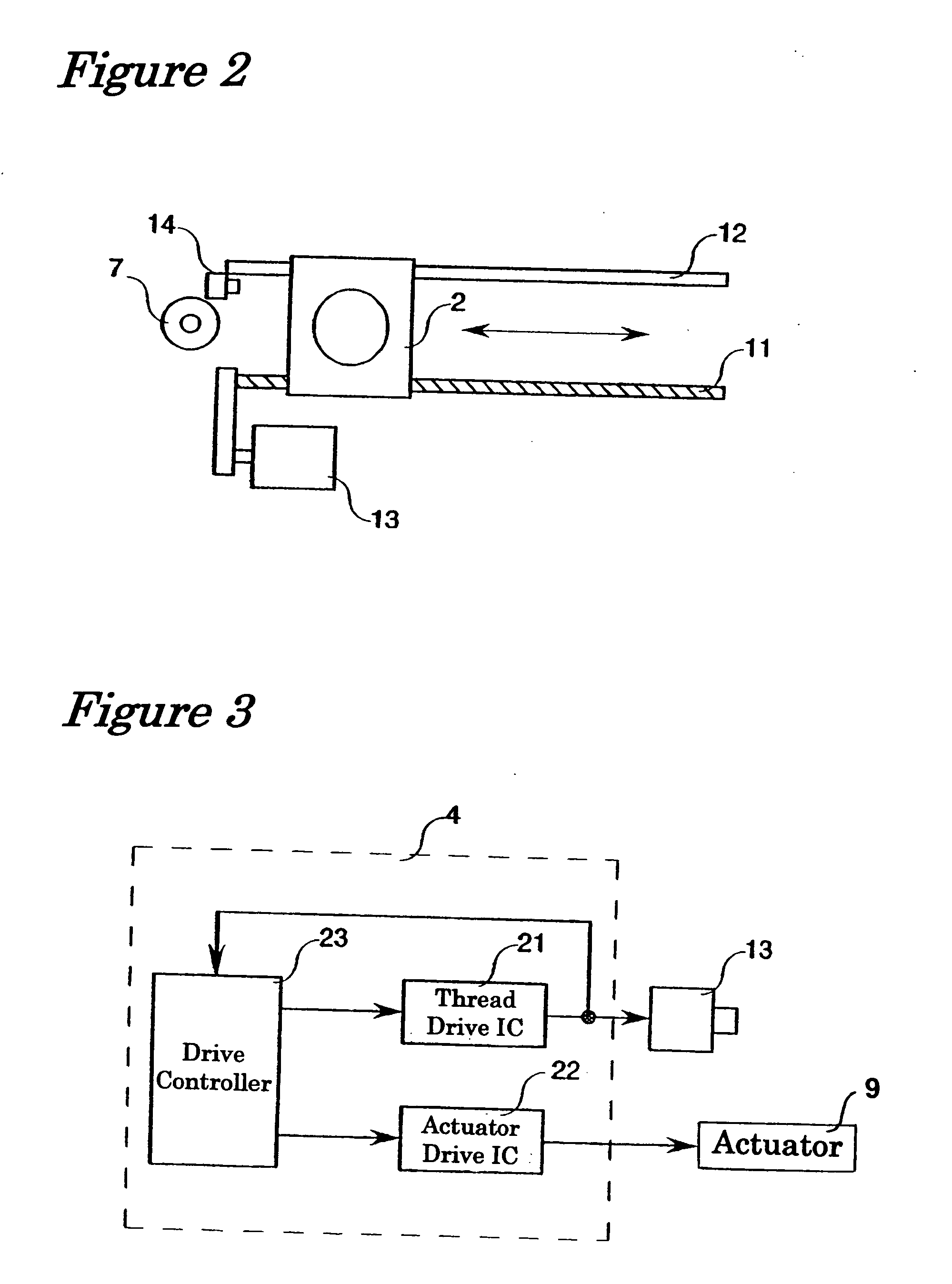
[0021] With this constitution, the correction value can be calculated while taking into account any offset voltage actually supplied by the drive IC to the moving means, which further reduces variance in the re-zeroing position among optical disk devices.
[0027] With this construction, the correction of the directed voltage is performed both with the operation of moving the pickup head to the innermost peripheral position, and the operation of moving the pickup head by a specific distance toward the outer periphery so as to position the pickup head at the initial track of the optical disk (hereinafter this operation will be referred to as “re-zeroing”). Accordingly, the reliability is improved and the device is easy for the user to use.

Problems solved by technology

A problem is that the above-mentioned variance in amplification factors among the drive ICs results in variance in the track-on position at which the pickup head is positioned at the end of the re-zeroing (this position will hereinafter be referred to as the re-zeroing position) among different optical disk devices.
Although it is possible to start tracking at the proper re-zeroing position by changing the drive voltage, but this retry operation takes extra time.

Method used


Image

  • Optical disk device and track-on method thereof
  • Optical disk device and track-on method thereof
  • Optical disk device and track-on method thereof

Examples


Embodiment Construction

[0034] Selected embodiments of the present invention will now be explained with reference to the drawings. It will be apparent to those skilled in the art from this disclosure that the following descriptions of the embodiments of the present invention are provided for illustration only and not for the purpose of limiting the invention as defined by the appended claims and their equivalents.

[0035] An optical disk device that is an embodiment of the present invention will now be described.

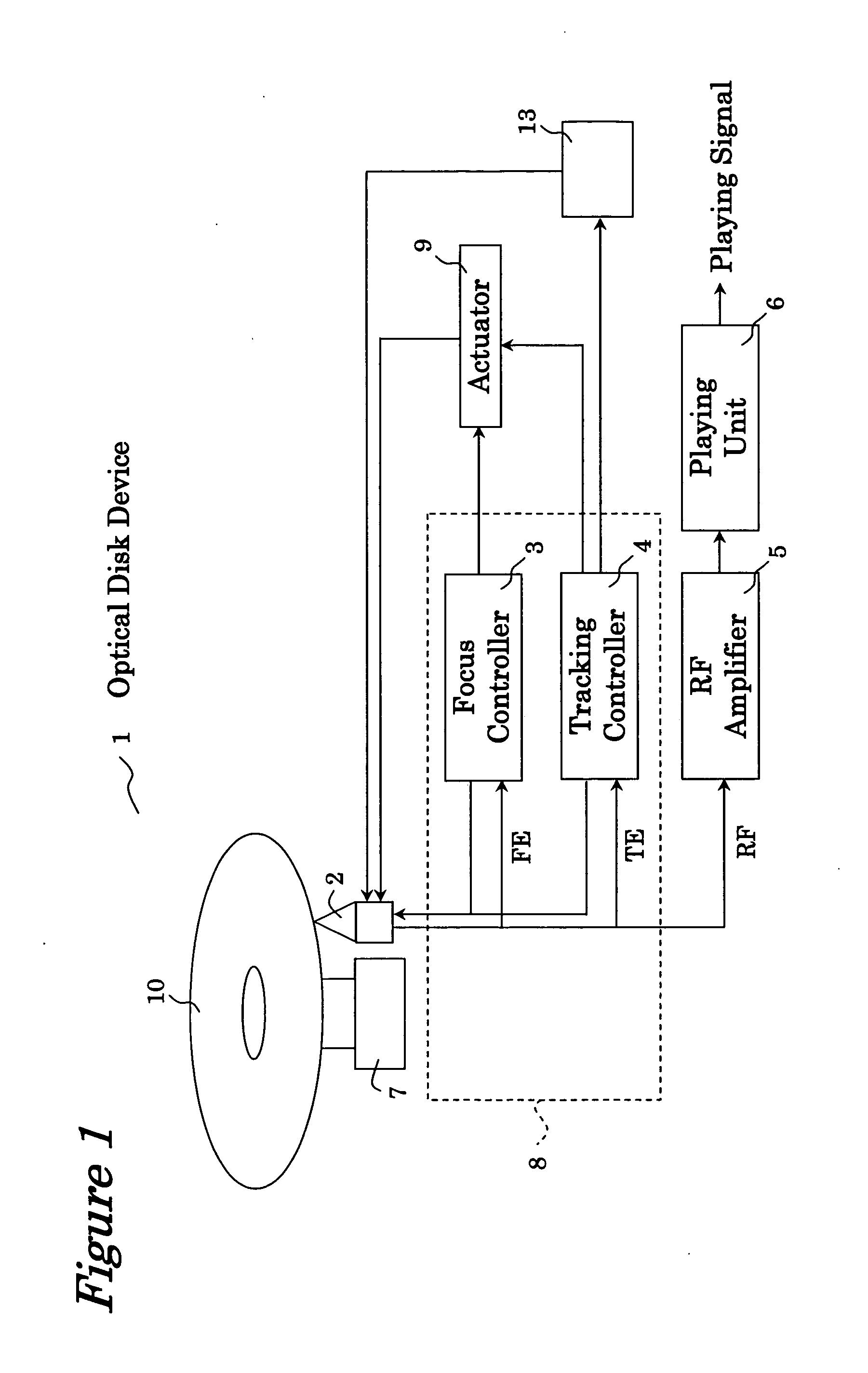
[0036]FIG. 1 is a schematic diagram of the constitution of the main components of the optical disk device in accordance with an embodiment of the present invention. The optical disk device 1 in this embodiment includes a pickup head 2 that directs a laser beam at an optical disk 10 mounted in the optical disk device, an RF amplifier 5 that amplifies an RF signal generated when the data recorded on the optical disk 10 are read, a playing unit 6 that generates and outputs a playing signal based on th...


PUM

PropertyMeasurementUnit
voltageaaaaaaaaaa
supplied voltageaaaaaaaaaa
drive voltageaaaaaaaaaa

Abstract

An optical disk device includes a pickup head, a thread motor, and a drive controller, and a thread drive IC. The drive controller supplies directed voltage to the thread drive IC. The thread drive IC in response supplies drive voltage to the thread motor, which moves the pickup based on the drive voltage from the thread drive IC. The drive controller directs to the thread drive IC supply of first directed voltage. The thread drive IC supplies first supplied voltage to the thread motor in response to the directive from the drive controller to supply the first directed voltage. The drive controller detects the first supplied voltage and calculates a correction value based on the detected first supplied voltage. The drive controller corrects the directed voltage with the correction value and then directs to the thread drive IC supply of a corrected drive voltage.

Description

BACKGROUND OF THE INVENTION [0001] 1. Field of the Invention [0002] The present invention relates to an optical disk device that reads data recorded in a CD, DVD or other such optical disk, and records data to such optical disk. The present invention also relates to a track-on method of a pickup of such optical disk device. [0003] 2. Background Information [0004] Optical disk devices that read data recorded in a CD, DVD or other such optical disks and record data to such optical disk have become hugely popular. As shown in Japanese Patent Application Publications Nos. 2002-93081 and 2000-11393, such optical disk devices are equipped with a pickup head. Such pickup head reads data recorded in an optical disk by directing a laser beam at an optical disk that is mounted in a main unit of the optical disk device, and detecting the light reflected by the optical disk. [0005] The pickup head is provided with a laser diode (LD) that functions as the light source, an objective lens for focu...

Claims


Application Information

Patent Timeline
Patent Type & Authority Applications(United States)
IPC IPC(8): G11B7/00
CPCG11B7/08505
Inventor TAKEDA, FUTOSHI
Owner FUNAI ELECTRIC CO LTD
Learn More