
Ferroelectric probe storage apparatus

a storage apparatus and probe technology, applied in the field of data storage devices, can solve the problems of high speed, low error-rate readout, and data can then be read out destructively

Inactive Publication Date: 2006-02-02
SEAGATE TECH LLC
View PDF8 Cites 103 Cited by
  • Summary
  • Abstract
  • Description
  • Claims
  • Application Information

AI Technical Summary

Problems solved by technology

A sense amplifier measures the charge flow that results when the polarization switches, so that a current pulse is observed for cells which stored a “0”, but not for cells which stored a “1”, thus providing a destructive readback capability.
Data can then be read out destructively by applying a voltage of a magnitude and polarity such as to cause the polarization to point “up”.
However, for a typical domain size of 25 nm×25 nm, desirable for a FE-Probe device, the resulting charge would be limited to about 6000 electrons, giving a current of about 1 nA for a read time of 1 microsecond, which makes high-speed, low error-rate readout difficult.
In addition, the readback is necessarily destructive, i.e. not preserving the original data.
Standard tips manufactured for Scanning Probe Microscopy (SPM) do not meet these requirements.

Method used


Image

  • Ferroelectric probe storage apparatus
  • Ferroelectric probe storage apparatus
  • Ferroelectric probe storage apparatus

Examples


Embodiment Construction

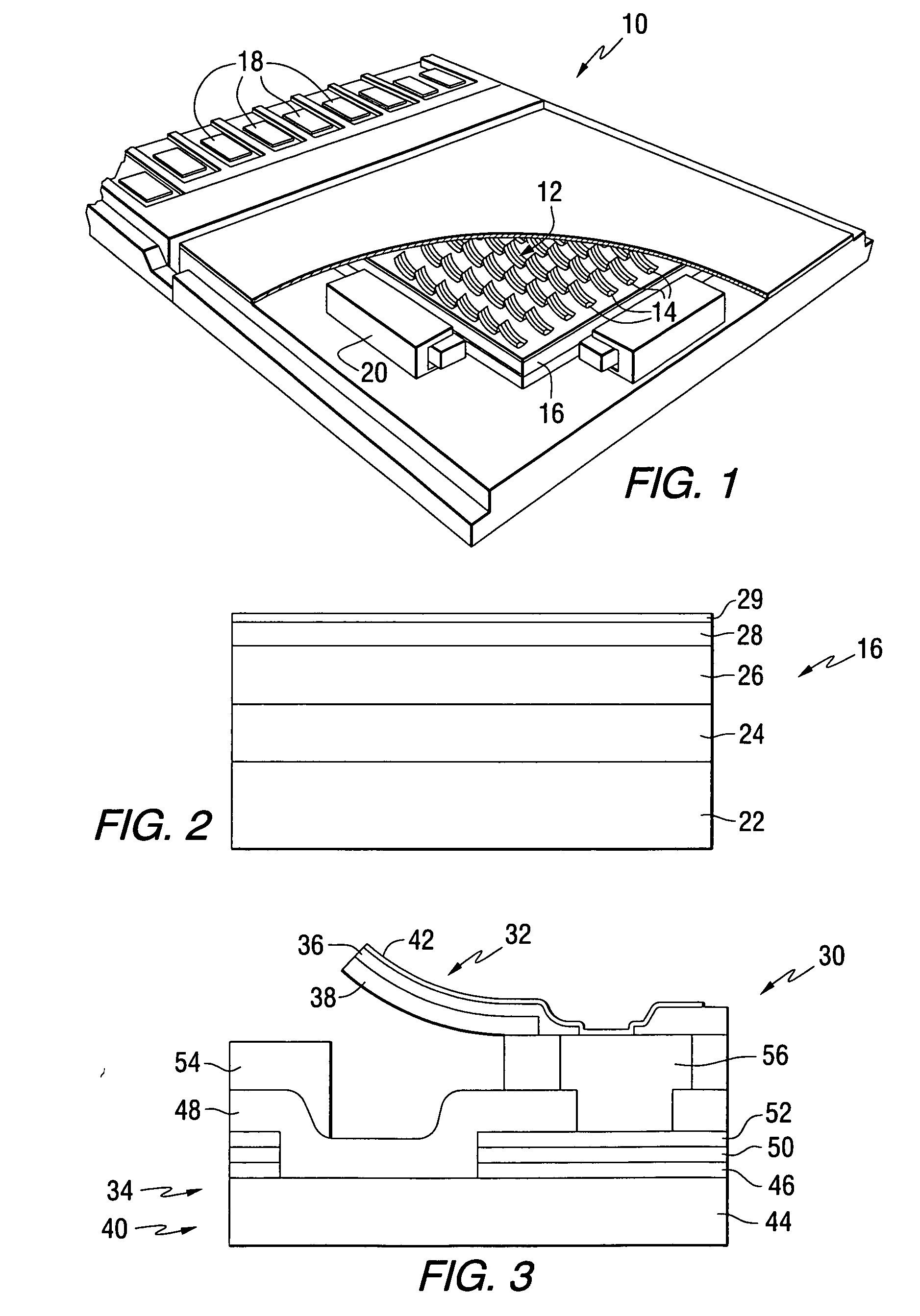
[0037] This invention provides probe storage devices that include a ferroelectric storage medium. FIG. 1 is a perspective view of a ferroelectric storage device 10 which illustrates an implementation of a storage system constructed in accordance with the present invention. In the ferroelectric storage device 10 of FIG. 1, an array 12 of ferroelectric heads 14 is positioned adjacent to a storage medium 16. In the configuration shown in FIG. 1 the array 14 and the medium 16 are planar and extend generally parallel with each other. The array 14 comprises a plurality of electrodes which are operably coupled to connectors 18. The storage medium 16 is coupled to at least one actuator 20 which is configured to move the medium 16 relative to array 12. This movement causes the ferroelectric heads to be moved relative to the individual ferroelectric domains on medium 16. Each head can include one or more electrodes. To address the destructive readback of data, one technique maintains at least...


PUM


Abstract

An apparatus comprises a ferroelectric storage medium, and a transducer for reading data from the ferroelectric storage medium and for writing data to the ferroelectric storage medium, wherein the transducer includes a substrate and a probe coupled to the substrate, wherein the probe includes a conductive element and a bilayer structure causing the probe to bend toward the ferroelectric storage medium.

Description

FIELD OF THE INVENTION [0001] This invention relates to data storage devices, and more particularly to probe storage devices that include ferroelectric storage media. BACKGROUND OF THE INVENTION [0002] Ferroelectric materials can form the basis for data storage devices, where digital “1” and “0” levels are represented by the electric polarization of a ferroelectric film pointing “up” or “down”. Storage devices based on a ferroelectric storage medium include Ferroelectric Random Access Memory (FeRAM) and scanning-probe storage systems (“FE-Probe”). [0003] In an FeRAM memory cell the essential storage element includes a thin ferroelectric film sandwiched between fixed, conductive electrodes. To write a bit to such a cell, a voltage pulse of either positive or negative polarity is applied between the electrodes in order to switch the internal polarization of the ferroelectric film to the “up” or “down” state, respectively. To read back the data from the FeRAM cell, a read voltage of a ...

Claims


Application Information

Patent Timeline
IPC IPC(8): G11B7/00
CPCG11B9/02
Inventor LUTWYCHE, MARK IANJOHNS, EARL CHRZASZCZFORRESTER, MARTIN GERARDBEDILLION, MARK DAVIDROELOFS, ANDREAS KARLAHNER, JOACHIM WALTERROTTMAYER, ROBERT EARLLIEM, ANDRE YLSKALKO, EDWARD S.YANG, XUESHI
Owner SEAGATE TECH LLC
Learn More