Fixing arrangement

a technology of fixing arrangement and bolt, which is applied in the direction of threaded fasteners, screwing, pedestrian/occupant safety arrangements, etc., can solve the problems of unusual bolts that are necessary for fastening, save material and hence costs, and achieve fewer work steps, save material, and simple bolt

Active Publication Date: 2006-02-02
ROBERT BOSCH GMBH
View PDF3 Cites 19 Cited by
  • Summary
  • Abstract
  • Description
  • Claims
  • Application Information

AI Technical Summary

Benefits of technology

[0005] An example fastening assembly according to the present invention may have the advantage that now the bolt has a round head having a smooth surface and that hence a simpler bolt or an alternative fastening assembly is possible. This bolt is in particular more advantageous to manufacture, since on the one hand the engagement surface for the tool is eliminated, thus requiring fewer work steps for manufacturing the bolt, and also because the head can now be designed to be thinner than would be necessary in the case of a head that has an engagement surface. This saves material and hence also costs. The preassembly process of screwing in this bolt having only one engagement surface is neutral as regards costs compared to the bolt having two engagement surfaces, so that thereby the cost advantage gained by the simpler bolt is not reduced.
[0007] Furthermore, it is advantageous if the fastening assembly according to the present invention has a rotation guard as well as a translation guard. On the one hand, this facilitates the installation of the fastening assembly according to the present invention, while on the other hand securing the first component fastened to the second component against rotational or translational movements, so that the first component, for example the sensor housing, always remains in the correct position in the keyhole. This may be achieved by projections, which, once the components have been assembled through the keyhole, block rotational and translational movements. The projections are provided in the housing in such a way that they extend with a precise fit into the keyhole and thereby prevent a movement. It is also possible to design the projections in such a way that the first component has just a small amount of play. This is advantageous particularly also during the fastening process so as to simplify this work step.

Problems solved by technology

The disadvantage of the design approach presented in EP 898 087 B1 is that this unusual bolt is necessary for fastening.
This saves material and hence also costs.

Method used


Image

  • Fixing arrangement
  • Fixing arrangement
  • Fixing arrangement

Examples


Embodiment Construction

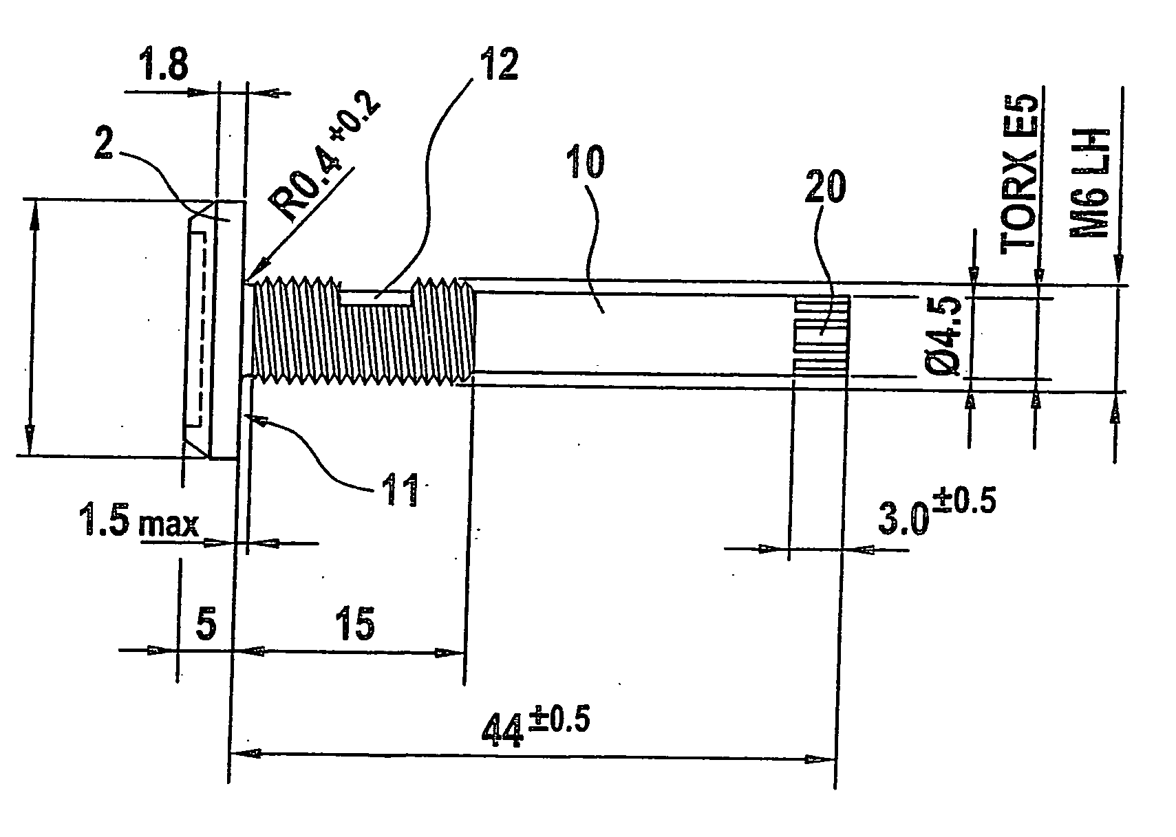
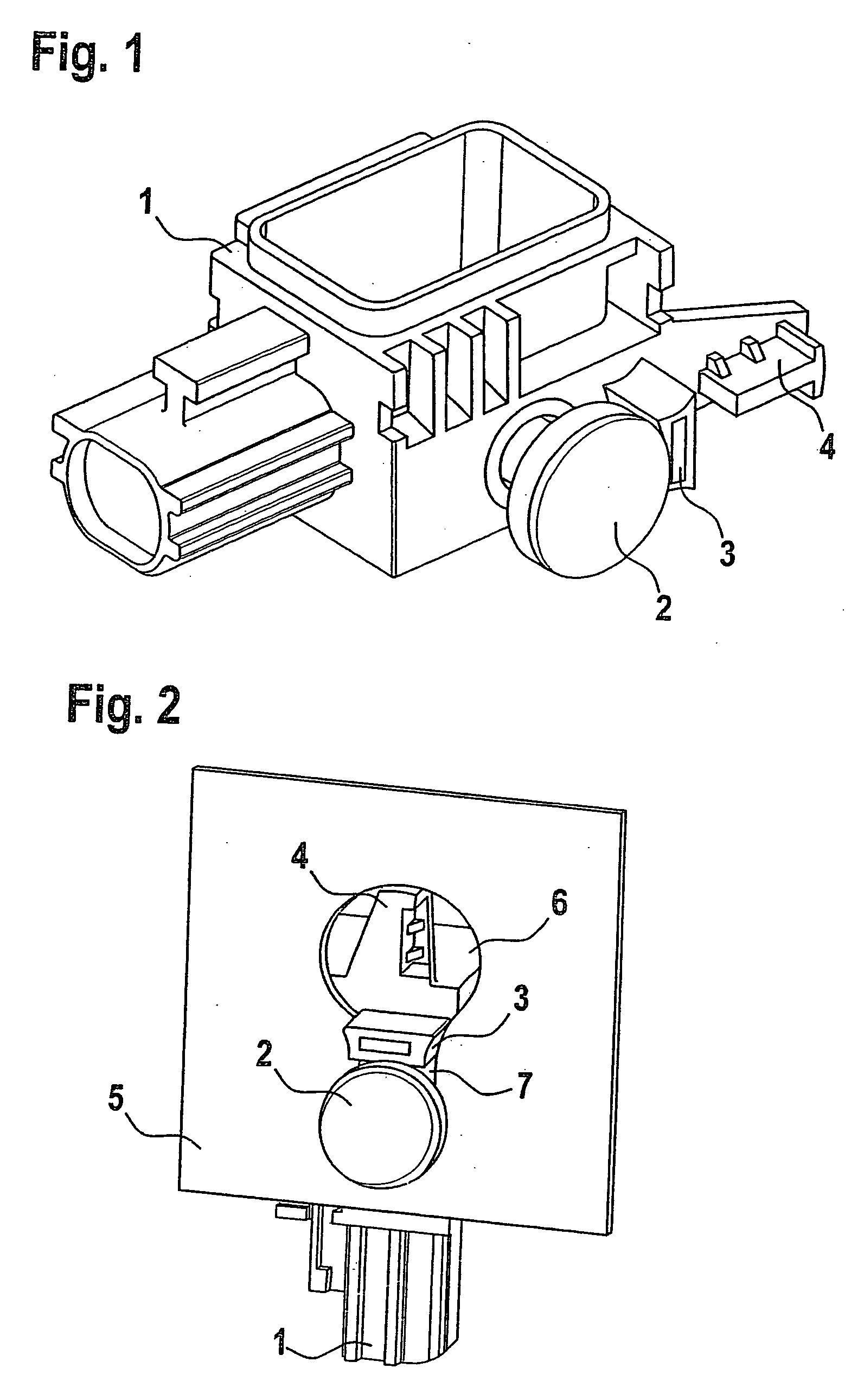
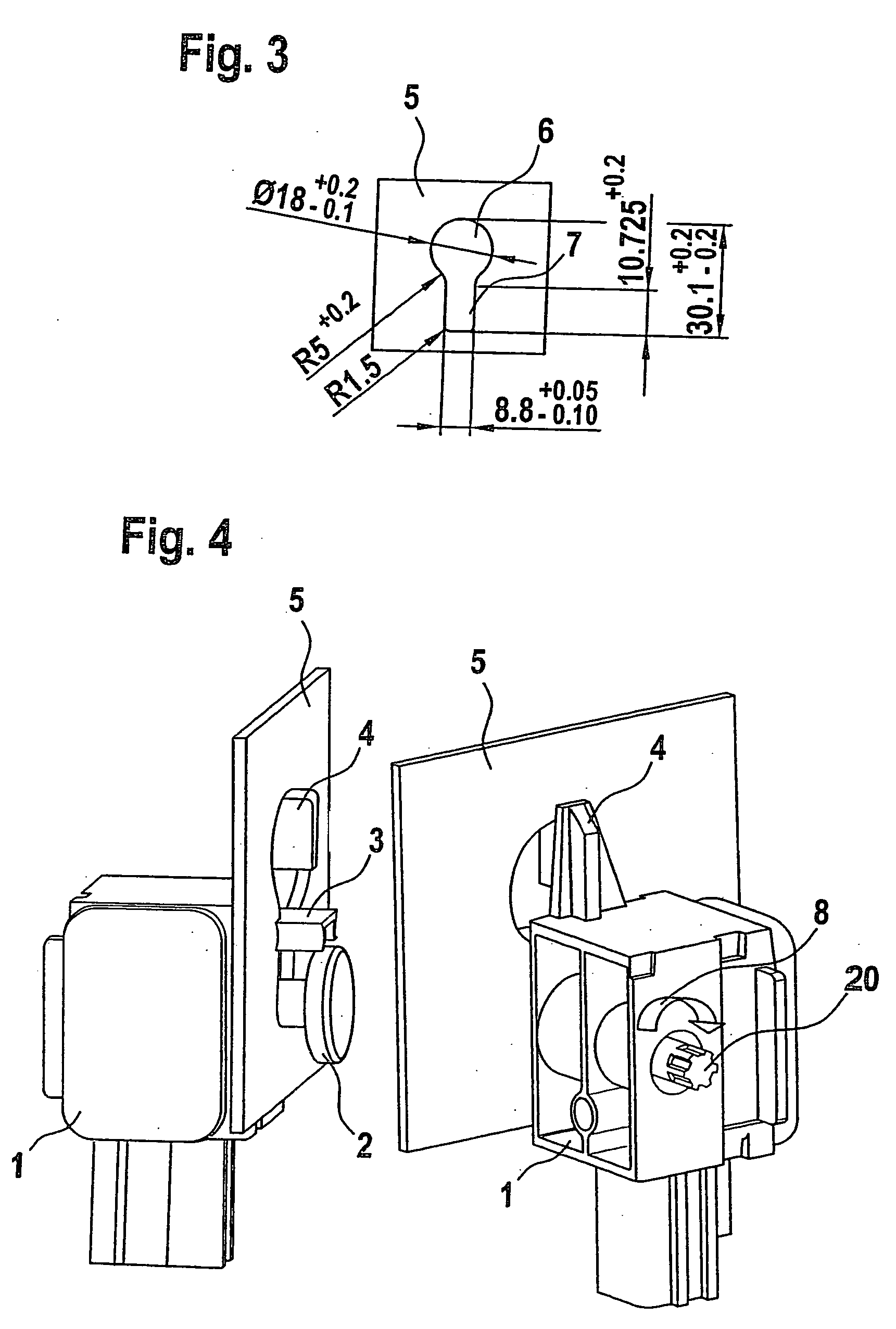
[0015] In the automotive industry, components, particularly sensors, for restraining systems for example, are fastened to the vehicle in various ways. Apart from screwing the component to a nut welded into the vehicle body or screwing the component via a hole in the vehicle body into a threaded bushing of the component using a bolt, the keyhole principle is increasingly used for fastening housings. For this purpose, bolts, preassembled and held in place by self-locking in a housing of the component to be mounted, are guided head first into the larger part of a keyhole-like cut-out in the vehicle body and are then hooked into the lower, narrower part, i.e. a further opening of the keyhole. The bolt is then tightened and the component thereby clamped.

[0016] In contrast to the two other methods mentioned above, the keyhole principle has the advantage that on the one hand no nut needs to be welded into or otherwise preinstalled in the vehicle, which represents a significant cost advant...


PUM


Abstract

A fastening assembly using the keyhole principle is provided. For this purpose, a first component having a bolt that has a round and smooth head is guided through the larger opening of the keyhole, in order then with the head to engage behind the smaller opening of the keyhole-like cut-out for fastening. At the end of its shank, the bolt preferably features an external toothing or an external polyhedron as engagement surface for a tool for fastening the first component to the second component.

Description

FIELD OF THE INVENTION [0001] The present invention relates to a fastening assembly. BACKGROUND INFORMATION [0002] European Patent No. EP 898 087 B1 describes a fastening assembly according to a keyhole principle, in which a bolt used for fastening has engagement surfaces for a tool at both ends. This unusual bolt makes it possible to clamp the fastening assembly from both ends. [0003] The disadvantage of the design approach presented in EP 898 087 B1 is that this unusual bolt is necessary for fastening. [0004] An object of the present invention, therefore, is to provide a fastening assembly that avoids this bolt. SUMMARY [0005] An example fastening assembly according to the present invention may have the advantage that now the bolt has a round head having a smooth surface and that hence a simpler bolt or an alternative fastening assembly is possible. This bolt is in particular more advantageous to manufacture, since on the one hand the engagement surface for the tool is eliminated,...

Claims


Application Information

Patent Timeline
Patent Type & Authority Applications(United States)
IPC IPC(8): F16B37/04F16B5/02F16B5/00F16B5/10F16B21/09F16B35/00F16B35/04
CPCF16B5/0036F16B35/045F16B21/09
Inventor FINK, ANDREASWOERNLE, WOLFGANG
Owner ROBERT BOSCH GMBH
Why Eureka
Try Eureka