Midplane especially applicable to an orthogonal architecture electronic system

a technology of orthogonal architecture and electronic system, applied in the direction of high frequency circuit adaptation, coupling device connection, electrical apparatus contruction details, etc., can solve the problems of significant difficulties in designing and fabricating midplanes, significant difficulties in dealing with electrical noise and other electrical characteristics, and increase of electrical noise between signal conductors

Active Publication Date: 2006-02-02
AMPHENOL CORP
View PDF47 Cites 118 Cited by
  • Summary
  • Abstract
  • Description
  • Claims
  • Application Information

AI Technical Summary

Benefits of technology

[0056]FIGS. 9A through 9D and FIGS. 10A through 10D illustrate the advantage of offset contact tails associated with the differential midplane connector 300 according to an embodiment the present invention. FIG. 9A illustrates a cross section through a traditional connector near the second contact end region. FIG. 9A shows that connector 300 has a pair-wise orientation. As used herein, “pair-wise” orientation indicates that the connector is designed with pairs of signal conductors adapted to preferentially electrically couple to each other. For example, the direction of the displacement between one conductor of a pair near the first contact end, e.g., 312(a), and the second conductor of the pair near the first contact end, e.g., 312(b), provides the orientation of the pair.

Problems solved by technology

As electronic systems have become smaller, faster and more complex, this has generally required that midplanes provide more vias and signal traces without increasing in size, or in many instances, while actually decreasing in size.
This has introduced significant difficulties in designing and fabricating midplanes, as well as significant difficulties in dealing with electrical noise and other electrical characteristics.
Electrical noise is usually considered any undesirable electrical energy in an electronic system, including but not limited to, reflections, electromagnetic interference, mode conversions and unwanted coupling, such as cross-talk.
A major difficulty with placing signal conductors closer together is that electrical noise between the signal conductors increases as the distance between signal conductors decreases and as the speed of the signals increases.
In addition, as frequency content increases, there is a greater possibility of energy loss.
Energy loss may be attributed to impedance discontinuities, mode conversion, leakage from imperfect shielding, or undesired coupling to other conductors (crosstalk).
However, use of a differential connector, especially in a midplane system architecture, introduces further difficulties as vias corresponding to the differential pair on either side of the midplane must each be electrically connected in the midplane and signal traces can only be routed between adjacent differential pairs.

Method used


Image

  • Midplane especially applicable to an orthogonal architecture electronic system
  • Midplane especially applicable to an orthogonal architecture electronic system
  • Midplane especially applicable to an orthogonal architecture electronic system

Examples


Embodiment Construction

[0029] This invention is not limited in its application to the details of construction and the arrangement of components set forth in the following description or illustrated in the drawings. The invention is capable of other embodiments and of being practiced or of being carried out in various ways. Also, the phraseology and terminology used herein is for the purpose of description and should not be regarded as limiting. The use of “including,”“comprising,”“having,”“containing,”“involving,” and variations thereof herein, is meant to encompass the items listed thereafter and equivalents thereof as well as additional items.

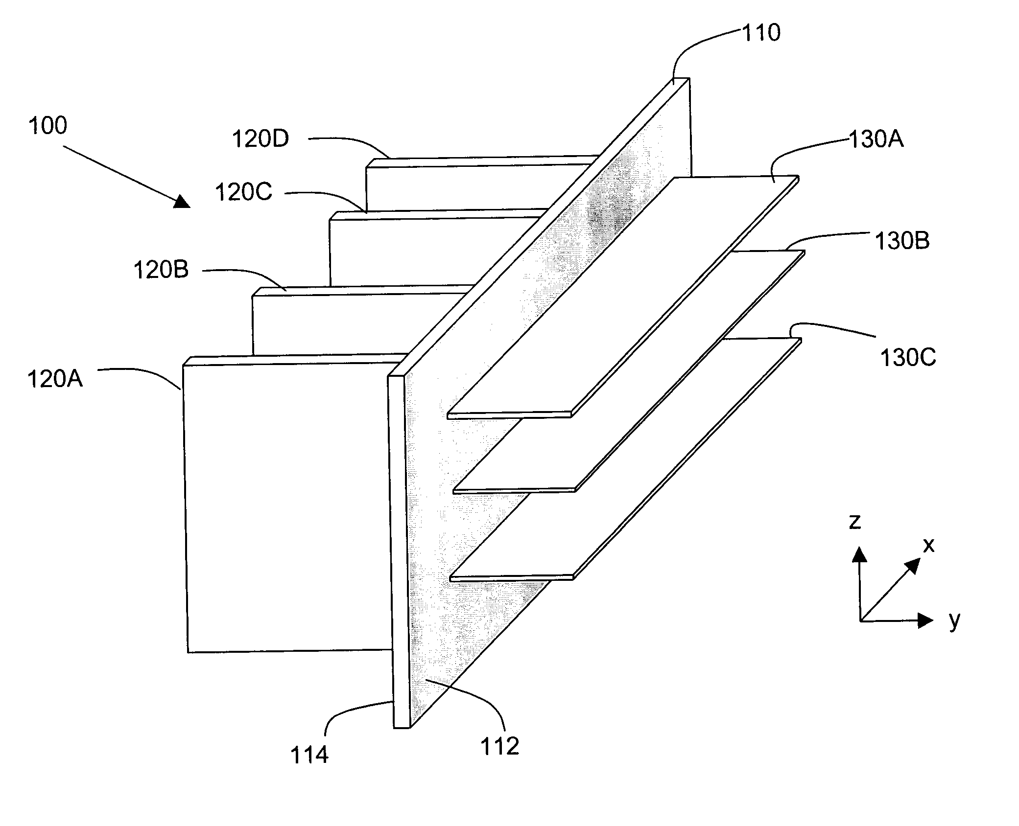
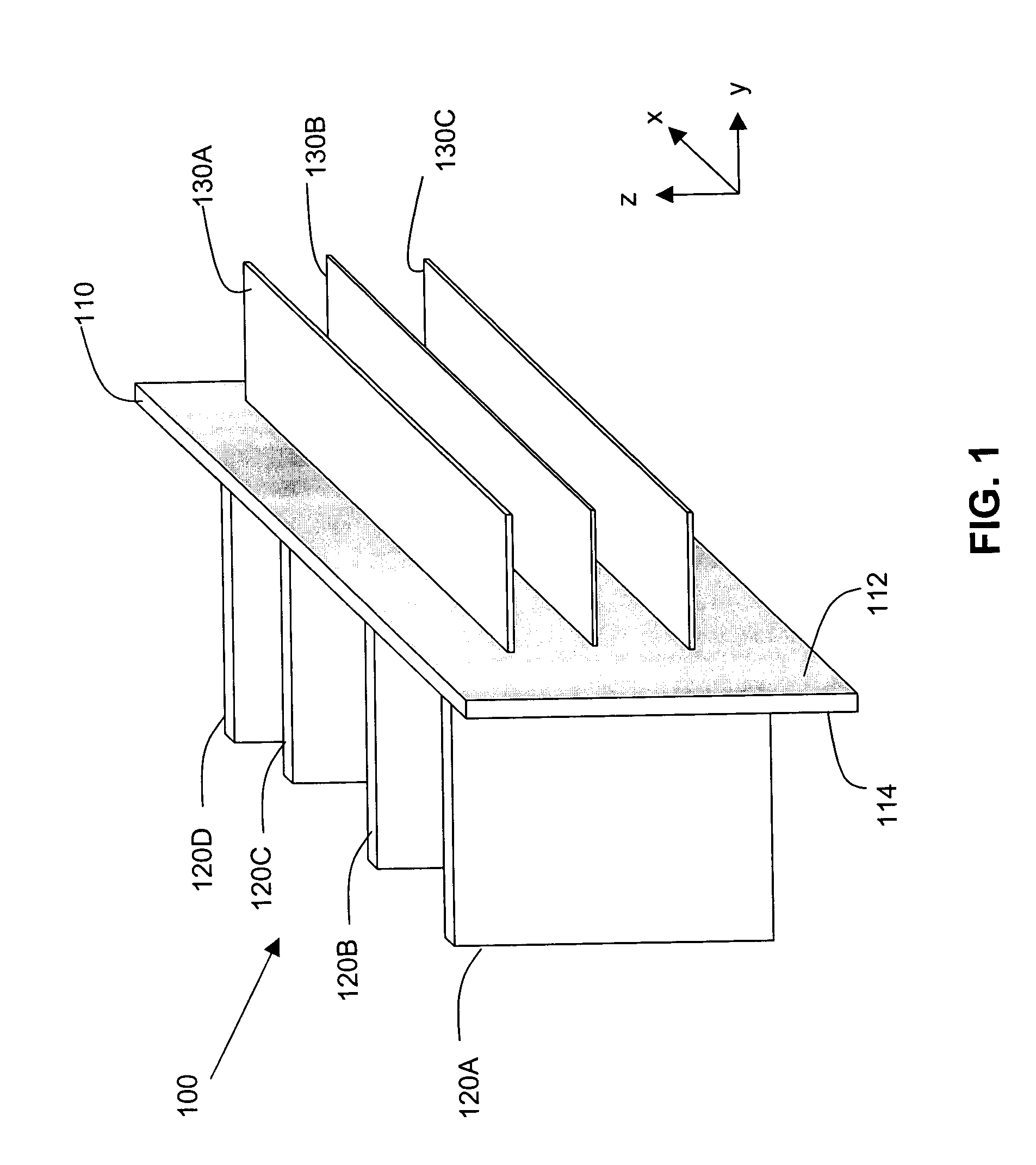
[0030] Referring to FIG. 1, there is shown a sketch of an electronic system 100 which utilizes a midplane 110 in accordance with the present invention. The midplane has a first side 112 and a second side 114. Daughtercards 120A, 120B, 120C and 120D are electrically connected to the midplane 110 on the second side 114. Daughtercards 130A, 130B and 130C are electric...


PUM


Abstract

A midplane has a first side to which contact ends of a first differential connector are connected and a second side opposite the first side to which contact ends of a second differential connector are connected. The midplane includes a plurality of vias extending from the first side to the second side, with the vias providing first signal launches on the first side and second signal launches on the second side. The first signal launches are provided in a plurality of rows, with each row having first signal launches along a first line and first signal launches along a second line substantially parallel to the first line. The second signal launches are provided in a plurality of columns, with each column having second signal launches along a third line and second signal launches along a fourth line substantially parallel to the third line.

Description

CROSS-REFERENCE TO RELATED APPLICATIONS [0001] This patent application claims priority to U.S. Provisional Patent Application No. 60 / 584,928, filed Jul. 1, 2004, and U.S. Provisional Patent Application No. 60 / 638,973, filed Dec. 24, 2004, the disclosures of which are incorporated by reference herein.BACKGROUND OF THE INVENTION [0002] Modern electronic systems are typically assembled from multiple printed circuit boards. Such printed circuit boards, which are commonly referred to as “daughter cards”, contain components thereon, such as integrated circuits. Each daughter card also typically includes one or more connectors that allow the components on the daughter card to communicate with components on the other daughter cards in the system. [0003] One way to interconnect the daughter cards in an electronic system is to utilize a midplane. A midplane is a printed circuit board, typically larger than the daughter cards, to which the daughter cards are connected—by way of connectors on b...

Claims


Application Information

Patent Timeline
Patent Type & Authority Applications(United States)
IPC IPC(8): H01R12/00H01R13/6469H01R13/6474H01R13/658H01R13/6585
CPCH01R13/514H01R23/688H05K1/0231H05K1/0237H05K1/116H05K1/14H05K2203/1572H05K7/1445H05K2201/044H05K2201/09236H05K2201/09718H05K2201/10189H05K3/429H01R13/6587H01R13/6591H01R12/00
Inventor COHEN, THOMAS S.CARTIER, MARC B. JR.GALLUS, MARK W.
Owner AMPHENOL CORP
Why Eureka
Try Eureka