Diversity receiving apparatus and wireless receiving apparatus using the same

a technology of receiving apparatus and receiving apparatus, which is applied in diversity/multi-antenna system, polarisation/directional diversity, transmission monitoring, etc., can solve the problems of inability to accurately determine the received power, the convergence of feedback loop requires more time, and the antenna requires a long time. , to achieve the effect of comparing the levels of average power, reducing the difficulty of comparing average power levels, and measuring the average power in a short tim

Inactive Publication Date: 2006-02-02
WI FI ONE
View PDF21 Cites 42 Cited by
  • Summary
  • Abstract
  • Description
  • Claims
  • Application Information

AI Technical Summary

Benefits of technology

[0019] According to the diversity receiving apparatus of the present invention, during all or part of a time period during which pattern signals having the same pattern are received, the gain is fixed and the average powers of received signals received by each antenna are determined. Then, the antenna to receive data is determined based on the levels of the average powers. Therefore, it is not necessary to wait for a feedback loop to converge in order to determine the average powers of received signals received by each antenna, making it possible to measure the average powers in a short time. In addition, since the gain is fixed, a comparison of levels between average powers can be easily made. Further, since an averaging period during which an average power is determined has the same time length as one period of a pattern signal, the diversity receiving apparatus can determine an average power in the same waveform at each averaging period, regardless of the timing at which averaging is performed, whereby the average powers can be compared more accurately.
[0020] If the level of a received signal is too high, the gain is lowered and the average power is measured again, and then the antenna to be selected is determined. If the level of a received signal is too low, the gain is raised and the average power is measured again, and then the antenna to be selected is determined. Thus, it is possible to make a comparison of powers in a wide range from a weak electric field to a strong electric field accurately in a short time.
[0021] Accordingly, an antenna having the highest received power can be selected quickly for each arriving wireless packet, and thus it is possible to establish a stable communication even in circumstances where there are changes in transmission environment. In addition, even in the case of receiving wireless packets to be sent from a plurality of terminals, because an antenna can be selected for each wireless packet, a stable communication can be achieved.

Problems solved by technology

The above-described conventional configuration, however, is unable to accurately determine a received power unless a feedback loop made up of the AGC circuit 904 and the VCO 905 is converged.
In addition, in the case where there is a great difference in received power between the two antennas, the power to be inputted to the AGC circuit 904 changes abruptly at the moment of switching from one antenna to another, and thus convergence of the feedback loop requires more time.
Thus, the receiving side needs to select an antenna within a preamble period of several μsec; however, in the conventional configuration such as that described above, since the AGC for a received-power comparison takes a long time, the selection of an antenna requires a long time and accordingly it is not possible to select an antenna within a preamble period of several μsec.

Method used


Image

  • Diversity receiving apparatus and wireless receiving apparatus using the same
  • Diversity receiving apparatus and wireless receiving apparatus using the same
  • Diversity receiving apparatus and wireless receiving apparatus using the same

Examples


first embodiment

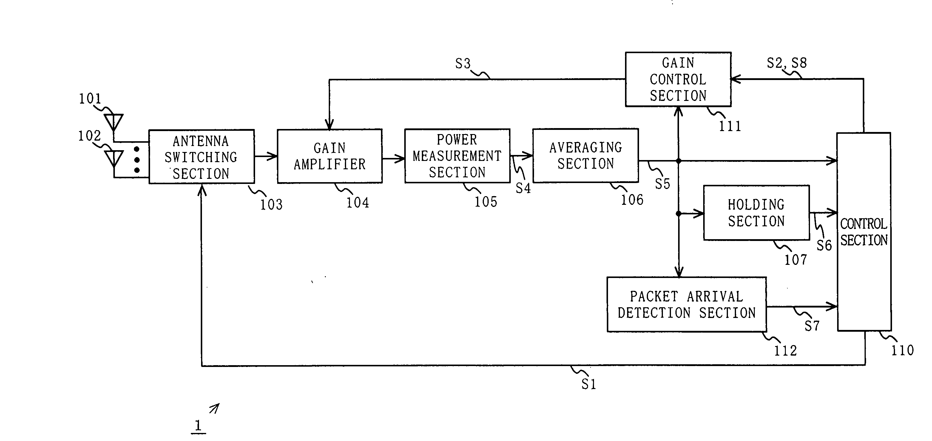
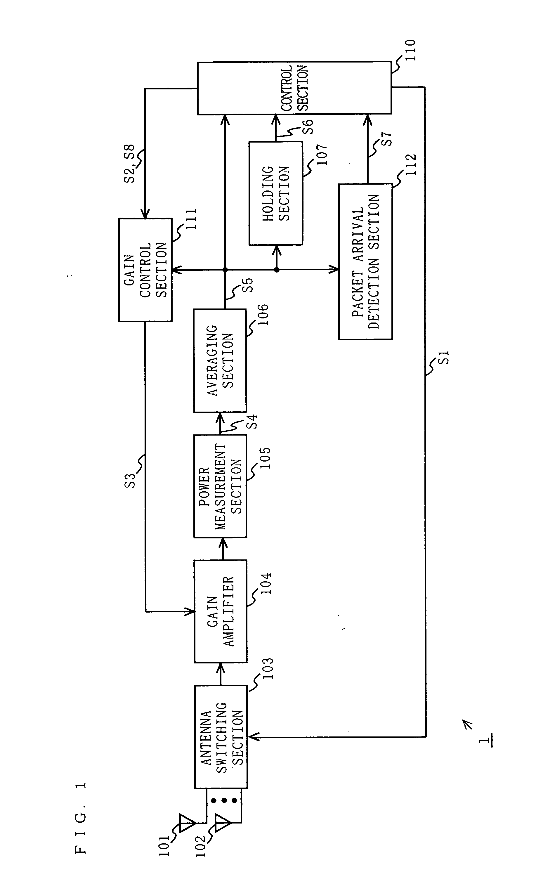
[0032]FIG. 1 is a block diagram showing a functional configuration of a diversity receiving apparatus 1 according to a first embodiment of the present invention. In FIG. 1, the diversity receiving apparatus 1 includes a plurality of antennas (e.g., a first antenna 101 and a second antenna 102); an antenna switching section 103; a gain amplifier 104; a power measurement section 105; an averaging section 106; a holding section 107; a packet arrival detection section 112; a control section 110; and a gain control section 111.

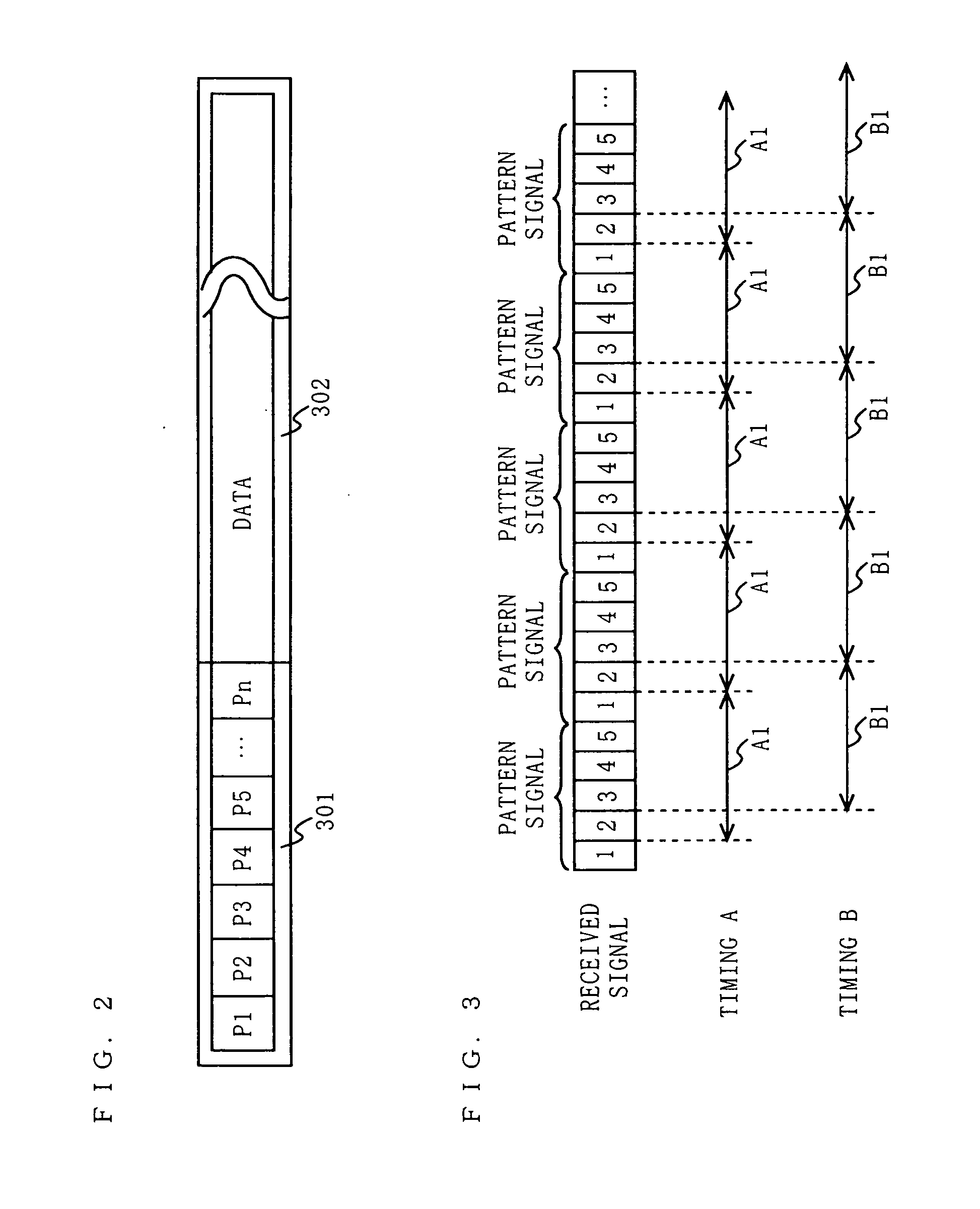
[0033]FIG. 2 is a diagram showing a frame configuration of a packet to be received by the diversity receiving apparatus 1 according to the first embodiment. A packet includes a preamble section 301 and a data section 302. In the preamble section 301, a pattern signal having a pattern P of a predetermined waveform is repeated multiple times. In FIG. 2, for description purposes, a first arriving pattern signal is indicated as “P1” and a next arriving pattern signal ...

second embodiment

[0060] The block configuration of a diversity receiving apparatus according to a second embodiment of the present invention is the same as that of the first embodiment, and thus FIG. 1 is incorporated herein. In using the first embodiment, in the case where a received power is very high, if the gain amplifier 104 amplifies a received signal with the first fixed gain, the measured value may be saturated in the power measurement section 105 and accordingly an instantaneous power may not be determined accurately. In view of this, in the second embodiment, in the case where a received power is very high, the control section 110 switches the gain to a second fixed gain which is lower than the first fixed gain to adjust the measured value so that the measured value is not saturated in the power measurement section 105, and then determines average powers for each selected antenna.

[0061]FIG. 5 is a timing chart showing the correlation between signals at the main portion of a diversity rece...

third embodiment

[0073]FIG. 6 is a block diagram showing a functional configuration of a diversity receiving apparatus 3 according to a third embodiment of the present invention. In FIG. 6, elements having the same functions as those in the first embodiment are denoted by the same reference numerals and the description thereof will be omitted. In FIG. 6, the diversity receiving apparatus 3 includes a plurality of antennas (e.g., a first antenna 101 and a second antenna 102); an antenna switching section 103; a gain amplifier 104; a power measurement section 105; an averaging section 106; a holding section 107; a correlation section 108; a correlation detection section 109; a control section 110a; and a gain control section 111a.

[0074] In the case of using the first embodiment, if a received power is very low, even if the gain amplifier 104 amplifies a received signal with the first fixed gain, the received signal may be buried in the noise level and an instantaneous power may not be measured accura...


PUM


Abstract

During all or part of a time period during which pattern signals are received, a diversity receiving apparatus allows a gain control section to fix the gain of a gain amplifier section, allows an antenna switching section to sequentially switch the selection of antennas during antenna switching periods which are synchronized with averaging periods, and determines an antenna to receive data contained in a packet, based on the levels of average powers measured by an averaging section on an averaging period-by-averaging period basis.

Description

TECHNICAL FIELD [0001] The present invention relates to a diversity receiving apparatus and a wireless receiving apparatus using the diversity receiving apparatus, and in particular to an antenna selection diversity receiving apparatus for selecting an antenna to receive a signal from a plurality of antennas and a wireless receiving apparatus using the antenna selection diversity receiving apparatus. BACKGROUND ART [0002] It is known that in mobile communications such as wireless LANs, the reception performance is degraded significantly by a fading phenomenon where the receiving electric field strength changes substantially due to reflection or scattering of radio waves. As reception techniques with which the influence of such a fading phenomenon is reduced, there are known diversity reception methods for selecting a signal to demodulate from received signals obtained from a plurality of reception systems. The diversity reception methods include an antenna selection diversity recept...

Claims


Application Information

Patent Timeline
Patent Type & Authority Applications(United States)
IPC IPC(8): H04B17/02H04B7/00H04B1/06H04B7/08H04B17/40
CPCH04B7/0808
Inventor SHIRAKATA, NAGANORIKIMURA, TOMOHIROHOSOKAWA, SHUYAHARADA, YASUO
Owner WI FI ONE
Why Eureka
Try Eureka