Communication controller with automatic time stamping

a communication controller and automatic time stamping technology, applied in the field of communication controllers, can solve the problems of general inability to use or be available to competitors, relative slowness,

Active Publication Date: 2006-02-02
FISHER-ROSEMOUNT SYST INC
View PDF10 Cites 332 Cited by
  • Summary
  • Abstract
  • Description
  • Claims
  • Application Information

AI Technical Summary

Benefits of technology

[0012] The present invention provides automatic time stamping of the messages transmitted and received by a device in a network, such as a process control system. The device generates event pulses corresponding to selected events associated with the transmitted and received messages. In response to those event pulses, current timer values within the device are stored as time stamp values.

Problems solved by technology

However, it is relatively slow.
Other companies in the industry have developed proprietary digital transmission schemes which are faster, but these schemes are generally not used by or available to competitors.

Method used


Image

  • Communication controller with automatic time stamping
  • Communication controller with automatic time stamping
  • Communication controller with automatic time stamping

Examples


Embodiment Construction

Process Control System Overview

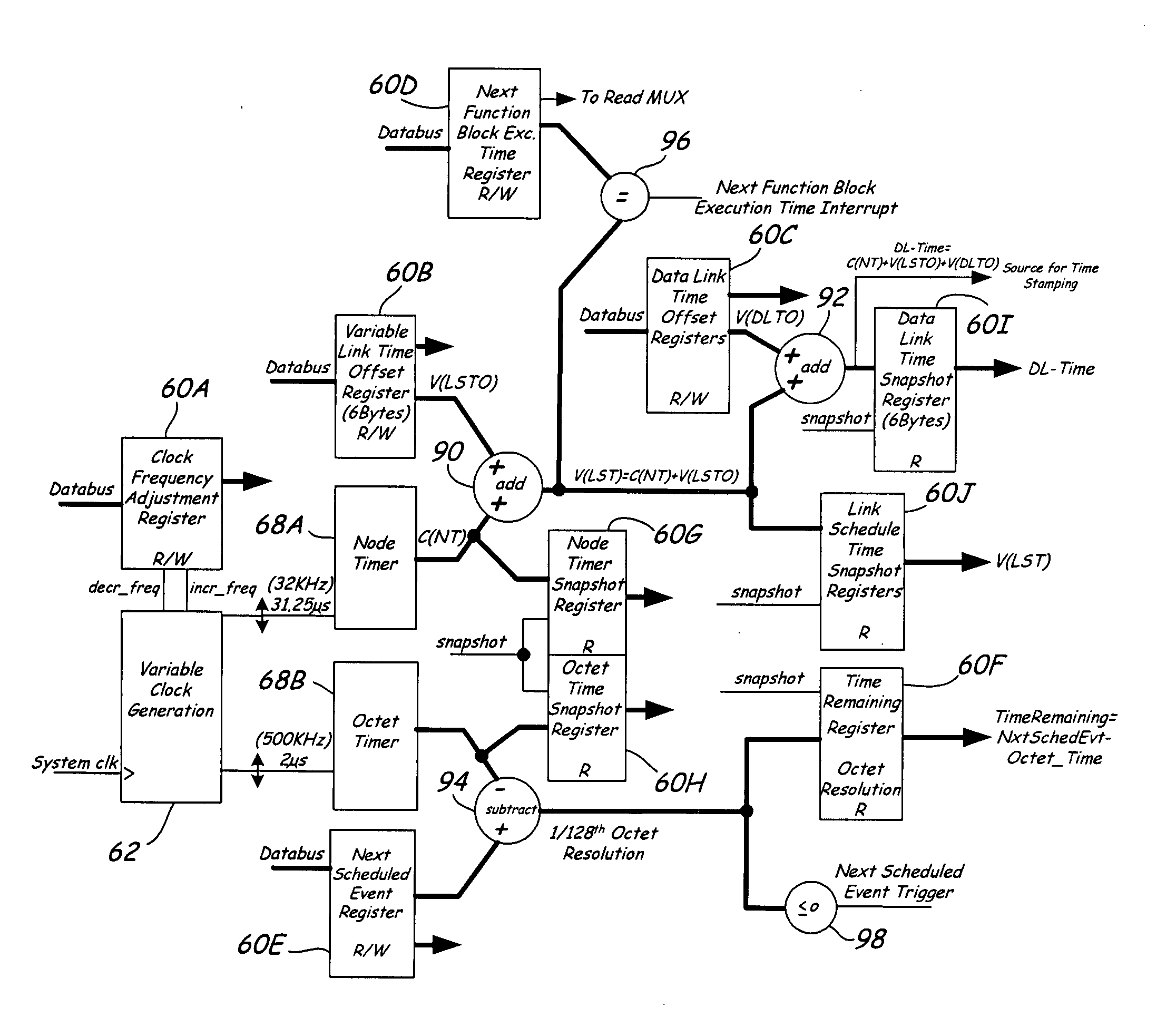
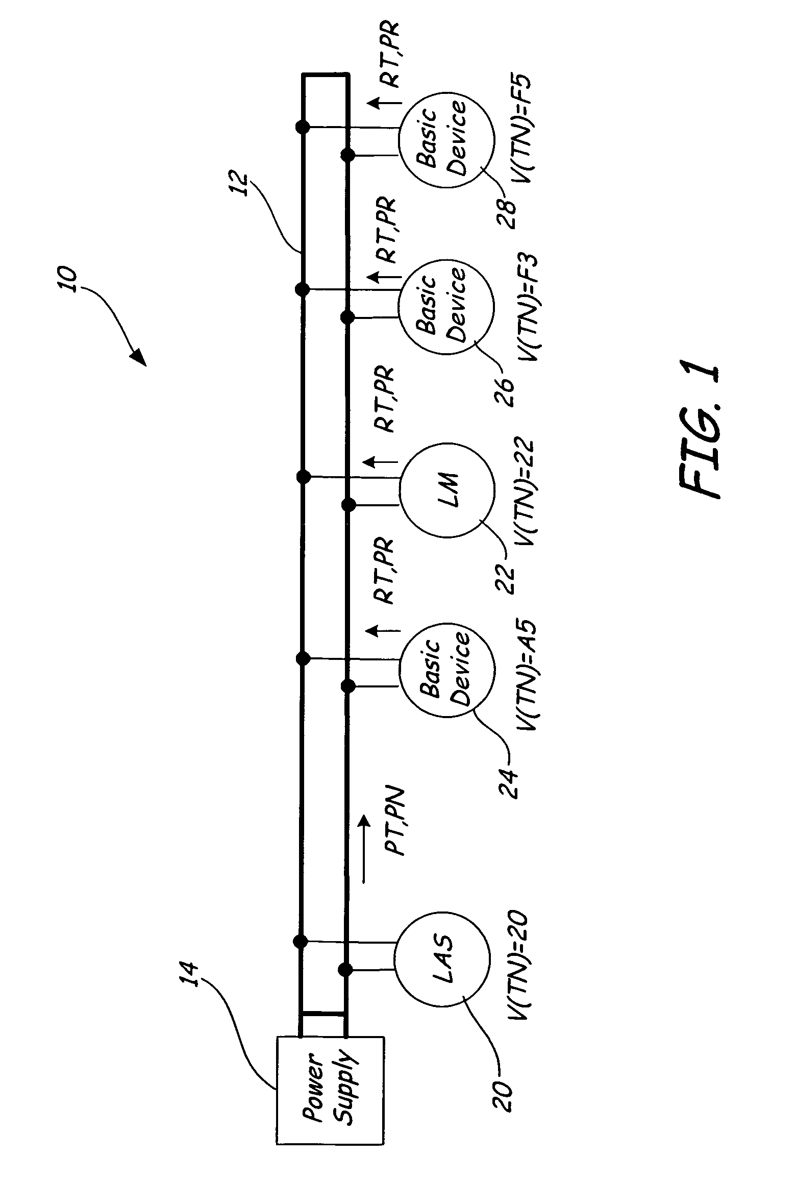
[0021] The present invention relates to a communication controller for use in field instruments and other devices of process control systems. The purpose of the communication controller is to perform a substantial portion of the link layer processing of messages and timer management, thereby freeing the application processor or CPU to perform other functions. For the purpose of this detailed description, the communication controller will be described in the context of a system using the Foundation Fieldbus communications protocol, although it has general applicability to packet-based communication protocols.

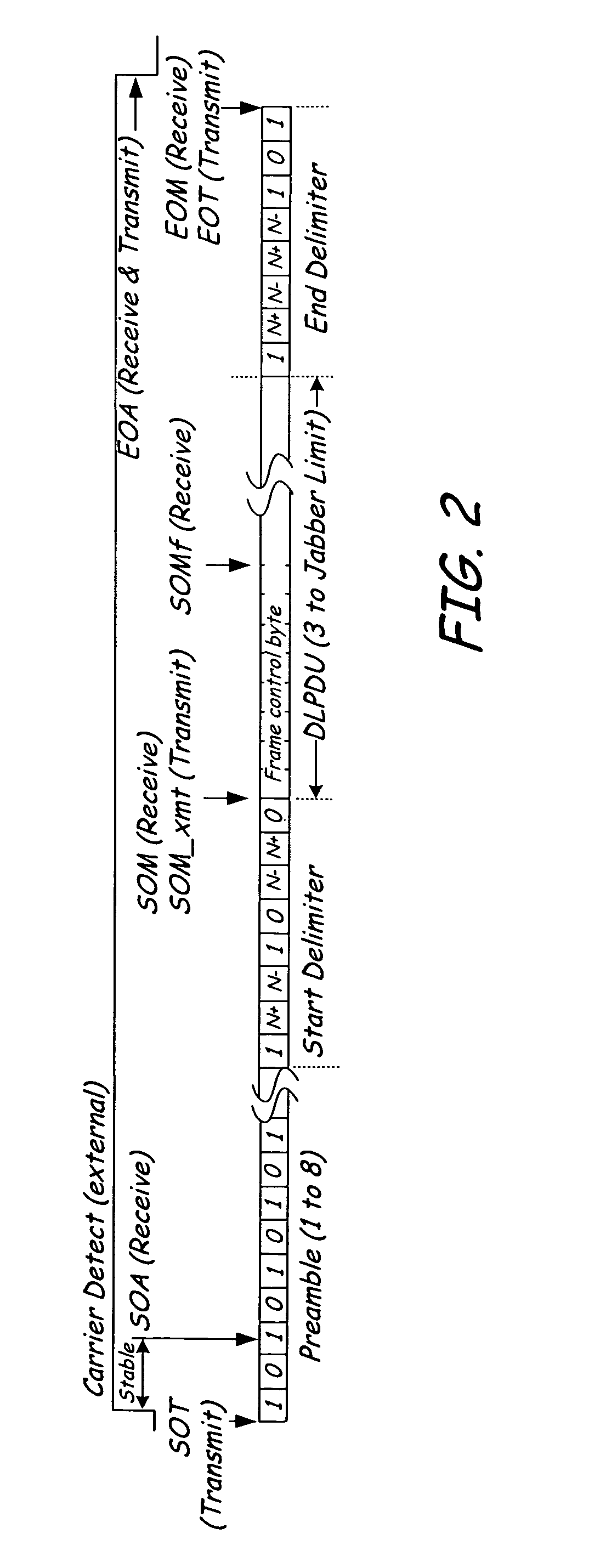
[0022] The fieldbus physical layer defines the electrical characteristics of the physical means of transmission and reception of the communications protocol data in the form of a Physical Layer Protocol Data Unit (PhPDU). In addition, the fieldbus physical layer specifies the symbol encoding, message framing, and error detection method. The ISA fi...


PUM


Abstract

Devices in a process control system communicate by data messages over a communication medium segment. Each device includes a communication controller that automatically time stamps events associated with received and transmitted messages.

Description

BACKGROUND OF THE INVENTION [0001] The present invention relates to a communications controller for use in field instruments and other devices of process control systems. In particular, the present invention is a system and method for low latency data packet reception and processing in a communications controller. [0002] In a typical industrial plant, a distributed control system (DCS) is used to control many of the industrial processes performed at the plant. Typically, the plant has a centralized control room having a computer system with user input / output (I / O), disc I / O, and other peripherals as are known in the computing art. Coupled to the computing system are a controller and a process I / O subsystem. [0003] The process I / O subsystem includes I / O ports which are connected to various field devices throughout the plant. Field devices include various types of analytical equipment, silicon pressure sensors, capacitive pressure sensors, resistive temperature detectors, thermocouple...

Claims


Application Information

Patent Timeline
Patent Type & Authority Applications(United States)
IPC IPC(8): G06F3/06
CPCG05B2219/31135H04L7/046H04L12/4135H04J3/0697H04L43/106H04L2012/40221H04L2012/4026H04L12/417
Inventor FRANCHUK, BRIAN A.BENSON, ROGER R.
Owner FISHER-ROSEMOUNT SYST INC
Why Eureka
Try Eureka