
Personal hygiene article with vibrating part and method

a technology of personal hygiene and vibrating parts, applied in the direction of carpet cleaners, cleaning using liquids, cell components, etc., can solve the problems of affecting the cleaning effect, so as to achieve the effect of cost-effectiveness and better cleaning action

Inactive Publication Date: 2006-02-09
TRISA HLDG AG
View PDF33 Cites 14 Cited by
  • Summary
  • Abstract
  • Description
  • Claims
  • Application Information

AI Technical Summary

Benefits of technology

[0006] An object of the present invention is to provide a cost-effective vibrating toothbrush which corresponds, in size, approximately to the conventional manual toothbrushes and nevertheless allows a better cleaning action than the latter.
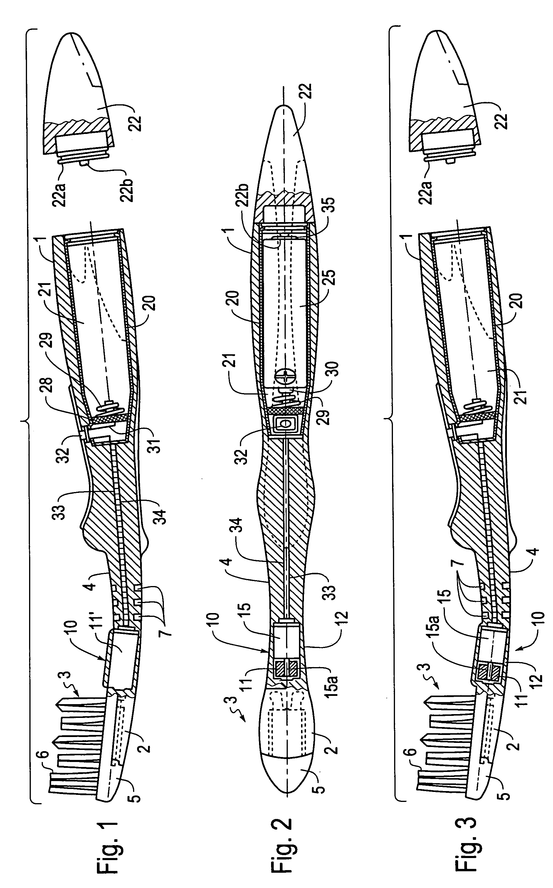
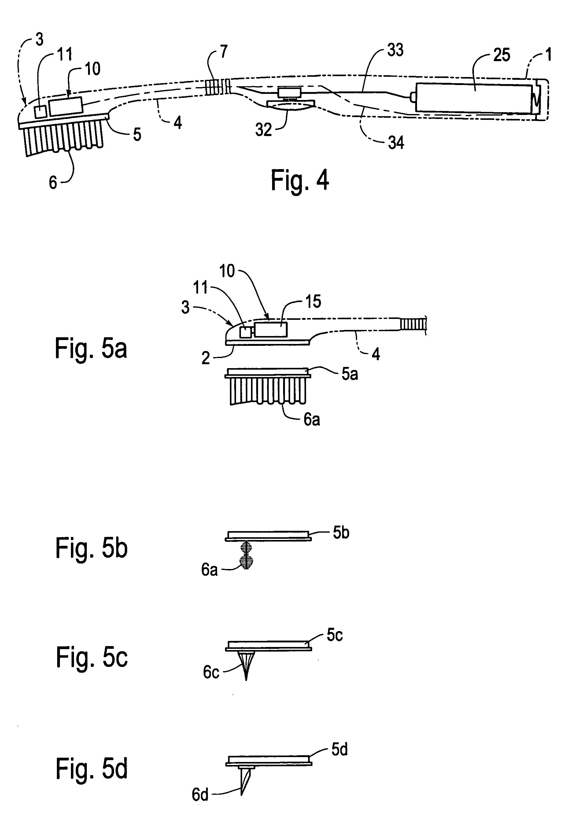
[0008] Since a mechanical vibratory device which causes the head part to vibrate is accommodated in a front head part of the toothbrush, or in a neck-part region adjacent to the head part, the neck part connecting the head part to the handle, and is operatively connected to a power source, preferably accommodated in the handle, via electrical connections running in the neck part, vibration-damping means preferably being provided in order to prevent vibration transmission to the handle, this achieves the situation where the vibrations which effect the improved cleaning action are produced predominantly in the head part and can only be felt to a slight extent in the handle, as a result of which comfortable handling of the toothbrush is achieved. A further advantage of the toothbrush according to the invention is that there is no need for any mechanical drive means to be led through the flexible neck part to the vibratory device. It is merely the electrical connections, designed as wires, cables or electrically conductive plastic tracks, which run through the neck part.

Problems solved by technology

Electric toothbrushes usually achieve a more intensive cleaning action than the manual toothbrushes, but they have the disadvantage that they are relatively bulky and expensive and may damage the gums and subject the tooth enamel to pronounced abrasion.

Method used


Image

  • Personal hygiene article with vibrating part and method
  • Personal hygiene article with vibrating part and method
  • Personal hygiene article with vibrating part and method

Examples


Embodiment Construction

[0017] Both the toothbrush illustrated in FIG. 1 and that according to FIGS. 2 and 3 each have a handle 1, a front bristle-carrying head part 3 and a neck part 4, which connects the head part 3 to the handle 1. The bristles combined to form clusters of bristles 6 are anchored in a bristle carrier 5 and form a possibly profiled brushing surface with their free ends. In the embodiment illustrated, the bristle carrier 5 with the clusters of bristles 6 is positioned, in a manner which is known per se and thus is not described in any more detail, on a retaining part 2 of the head part 3 such that it can be exchanged.

[0018] The neck part 4 is provided with neck-part zones 7 which are made of an elastically relatively compliant material component and provide for, or additionally increase, the elasticity of the neck part 4, with the result that, during use of the interdental treatment device, the head part 3 can be forced back resiliently in the case of forces acting in the direction of th...


PUM

PropertyMeasurementUnit
lengthaaaaaaaaaa
lengthaaaaaaaaaa
diameteraaaaaaaaaa

Abstract

A personal hygiene article, such as a toothbrush, includes a handle configured to accommodate an electric power source, a head carrying a treatment tool, and a neck between the handle and the head. The head or neck includes a mechanical motorized vibratory device, including a drive that causes the head to vibrate. Electrical connections are operably connected to the mechanical vibratory device and the electric power source to power the mechanical vibratory device via the electrical connections. In various embodiments, a vibration-damping structure dampens vibration transmission from the head to the handle.

Description

CROSS-REFERENCE TO RELATED APPLICATIONS [0001] This application is a Divisional of application Ser. No. 10 / 913,465 filed Aug. 9, 2004, which is a Divisional of application Ser. No. 10 / 093,699 filed Mar. 11, 2002, which is a Continuation of PCT / CH00 / 00563 filed Oct. 18, 2000, which claims priority from German Patent Application No. 199 50 204.8 filed Oct. 19, 1999 and German Patent Application No. 299 19 053.6 filed Nov. 3, 1999.BACKGROUND OF THE INVENTION [0002] 1. Field of Invention [0003] The invention relates to a personal hygiene article that includes an electrically powered vibrating head. [0004] 2. Description of Related Art [0005] For teeth-cleaning purposes nowadays use is made either of conventional manual toothbrushes or of electric toothbrushes, in the case of which a movable brush head can be motor-driven from the handle. Electric toothbrushes usually achieve a more intensive cleaning action than the manual toothbrushes, but they have the disadvantage that they are relat...

Claims


Application Information

Patent Timeline
Patent Type & Authority Applications(United States)
IPC IPC(8): A46B13/02B29C45/14A46B7/04A46B9/04A46B15/00A61C17/20A61C17/22A61C17/34
CPCA46B7/04H01M2/1055A46B13/023A46B15/0002A46B15/0016A46B15/0046A46B2200/1066A61C15/02A61C17/20A61C17/222A61C17/34A61C17/3481B29C45/14639B29C45/1671B29C2045/1673B29L2031/425A46B9/04Y02E60/10H01M50/213A61C2204/002
Inventor HAFLIGER, PETERFISCHER, FRANZELSTER, GUNTHER
Owner TRISA HLDG AG
Learn More