Device to control power source

Active Publication Date: 2006-02-09
LINCOLN GLOBAL INC
View PDF9 Cites 11 Cited by
  • Summary
  • Abstract
  • Description
  • Claims
  • Application Information

AI Technical Summary

Benefits of technology

[0014] The primary object of the present invention is the provision of a device for preventing operation of a power source

Problems solved by technology

In order to reduce the open circuit voltage to a low level, the minimum conduction period of the switching devices requires a complicated an

Method used


Image

  • Device to control power source
  • Device to control power source
  • Device to control power source

Examples


Embodiment Construction

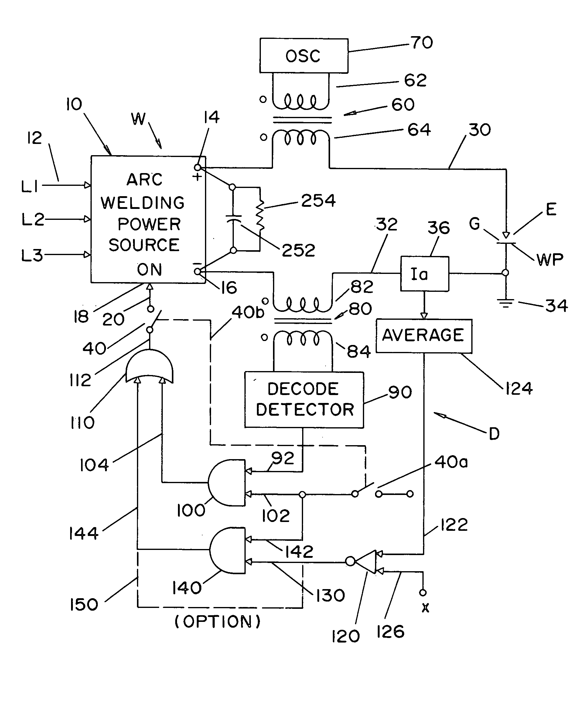
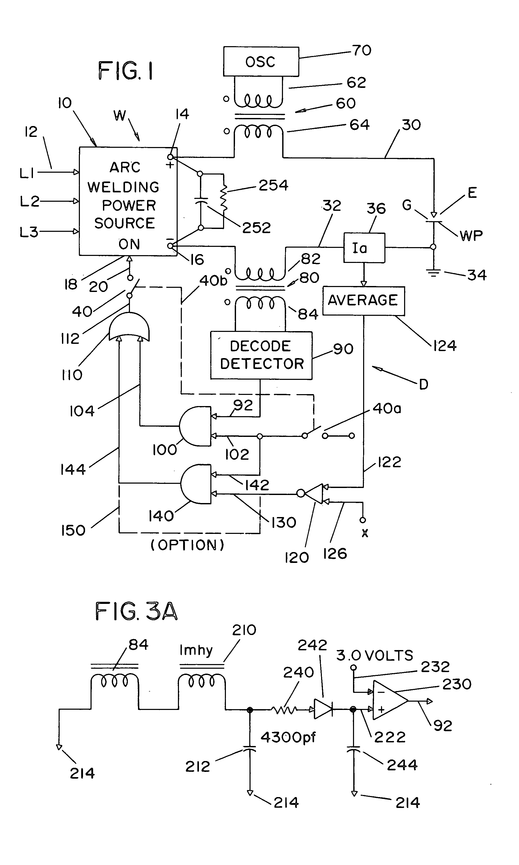
[0029] Referring to the drawings, wherein the showings are for the purpose of illustrating preferred embodiments of the invention only and not for the purposes of limiting same, FIG. 1 shows an electric arc welder W of the type used for AC or DC welding for MIG welding, TIG welding, stick welding and submerged arc welding in both CC and CV modes. Welder W includes power source 10 having a three phase input 12 and output terminals 14, 16 connected to welding cables 30, 32, respectively. The welding operation is schematically illustrated as an electrode E, which can be a consumable wire directed toward workpiece WP. Gap G is located between electrode E and workpiece WP and is used in standard welding technology. The average welding current is measured by shunt 36. When welding is performed by welder W, power source 10 is activated to provide power at terminals 14, 16. Power source 10 is preferably an inverter based power source having an ON terminal 18 controlled by the logic on input...


PUM

PropertyMeasurementUnit
Electrical resistanceaaaaaaaaaa

Abstract

A device to control operation of a power source for an electric arc welder comprising an oscillator for inducing a high frequency voltage into a series circuit including the welding gap, a detector tuned to the high frequency for sensing the level of current in the series circuit at the high frequency and an output circuit to create a start signal when the received signal level exceeds a given value representing a resistance in said gap below a given amount.

Description

[0001] The present invention relates to electric arc welding and more particularly to a device for controlling the operation of a power source for an electric arc welder having a first output terminal connectable to a first welding cable and a second output terminal connectable to a second welding cable where the cables are in a series circuit including a welding gap defined by an electrode and workpiece. BACKGROUND OF INVENTION [0002] Several techniques have been used to reduce the open circuit voltage of an arc welding power source before the welder is to be used for a welding process. One of the most common designs is a control circuit that reduces the conduction period of the output switching devices, so the open circuit voltage is retained at a desired lower value. In an inverter type power source, the switching devices are usually in the form of a FET or an IGBT. Since the switching frequency is usually greater than 20 kHz, the conduction period of these switching devices is v...

Claims


Application Information

Patent Timeline
IPC IPC(8): B23K9/10
CPCB23K9/0956
Inventor STAVA, ELLIOTT K.CLARK, KEITH L.
Owner LINCOLN GLOBAL INC
Why Eureka
Try Eureka