Horn switch gear, airbag system, and steering wheel

a horn switch and airbag technology, applied in the field of horn switches, can solve the problems of difficult positioning of horns with high accuracy, and achieve the effect of improving horn operability

Inactive Publication Date: 2006-02-09
TAKATA CORPORATION
View PDF3 Cites 18 Cited by
  • Summary
  • Abstract
  • Description
  • Claims
  • Application Information

AI Technical Summary

Benefits of technology

[0013] In contrast, with the aforementioned horn switch gear, the airbag system, and the steering wheel, the horn blowing signal is generated by a noncontact sensor. Accordingly, the sensor-activating member (e.g., a magnet) for causing the noncontact sensor (e.g., a Hall IC) to output the signal is operational provided it comes within a specified distance from the noncontact sensor, when the backward moving body is pushed backward, i.e., contact is not required. As the sensor activating member only has to be brought within a specified distance of the noncontact sensor, the required assembly accuracy of the horn switch gear (and the airbag system incorporating the horn switch gear) is reduced. Moreover, as the horn switch gear employs a noncontact system, it has high durability and does not affect the operating characteristics even if slight water enters the vicinity of the horn switch.
[0033] As the horn switch gear for vehicles according to the invention may have a structure in which the magnet and the magnetic coil are moved relatively by the depression of the second component by the occupant such that the horn is activated by the induced current generated by the relative movement, the horn operability may be improved.

Problems solved by technology

Unfortunately, as the contacts are disposed separately, it is difficult to position them with high accuracy.

Method used


Image

  • Horn switch gear, airbag system, and steering wheel
  • Horn switch gear, airbag system, and steering wheel
  • Horn switch gear, airbag system, and steering wheel

Examples


Embodiment Construction

[0045] Embodiments of the present invention will be described with reference to the drawings. Like numbers are used throughout the drawings to refer to the same or similar parts in each of the embodiments of the invention described herein.

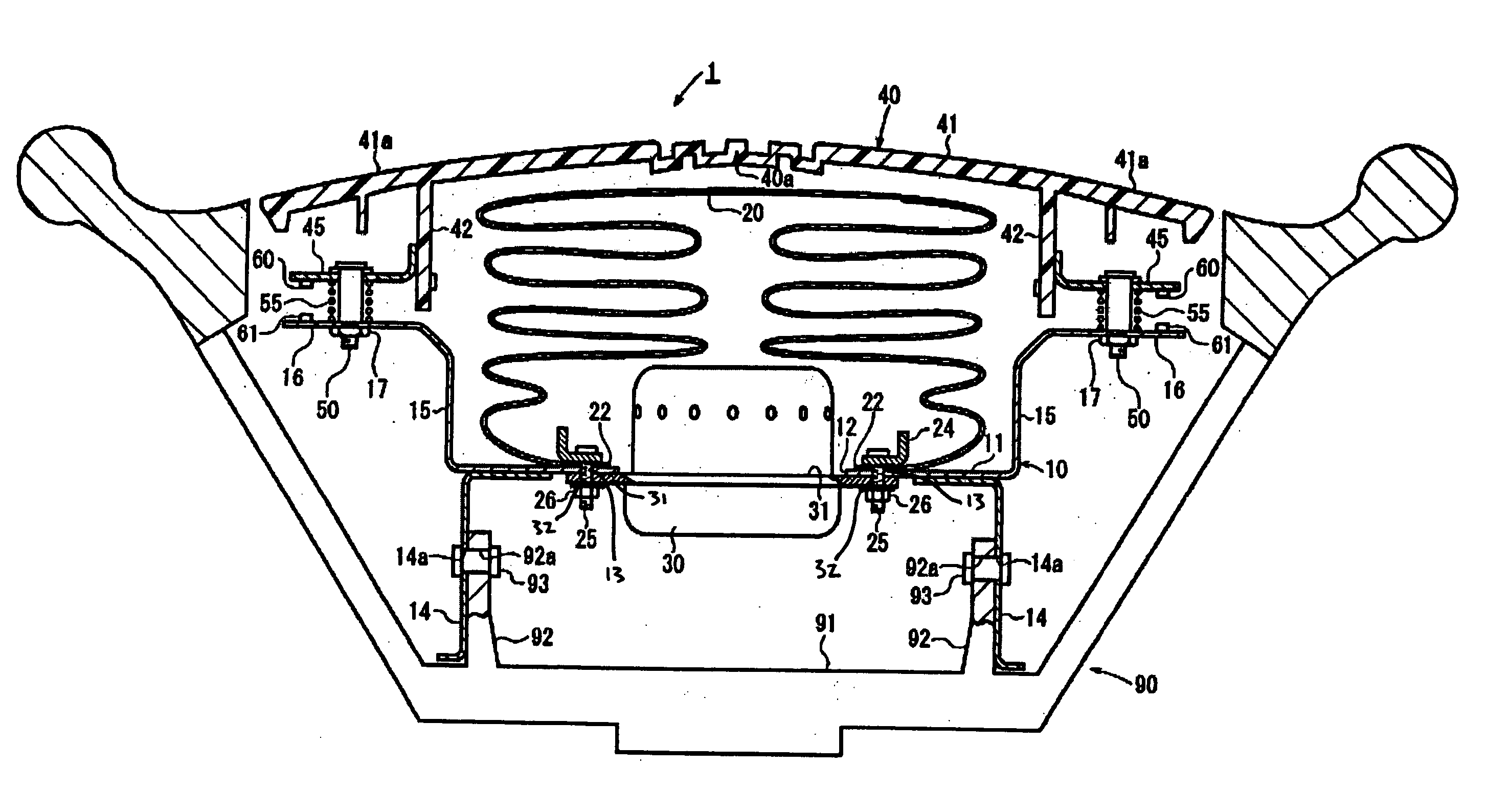
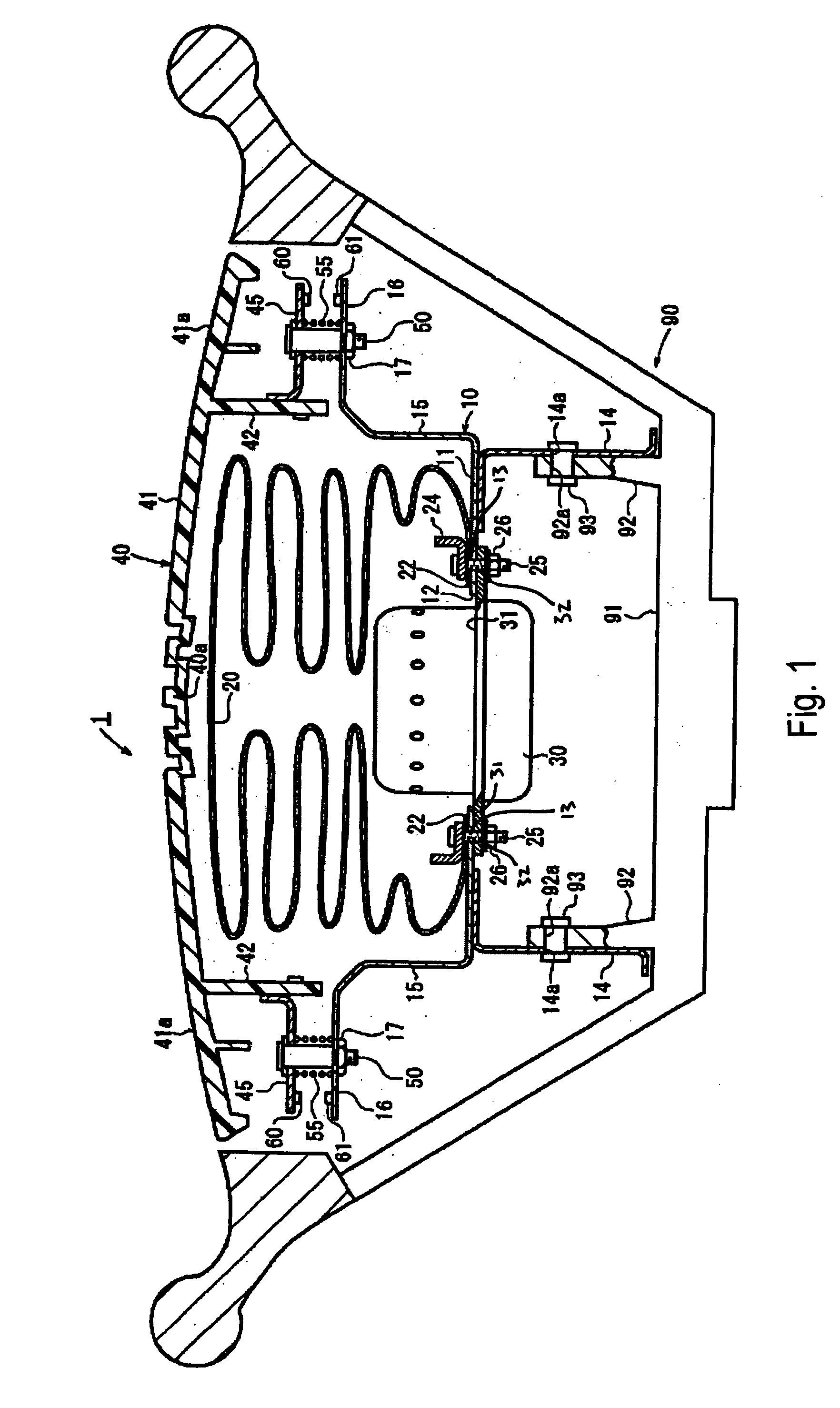
[0046]FIG. 1 is a cross-sectional view of a steering wheel 90 with an airbag system 1 that includes a horn switch gear according to an embodiment of the present invention. FIG. 2 is an enlarged view of the horn switch gear in FIG. 1.

[0047] The airbag system 1 is a driver-seat airbag system disposed in the center (base 91) of a steering wheel 90. The airbag system 1 includes a metal retainer 10, an airbag 20 mounted to the retainer 10 with an airbag-fixing ring 24, an inflator 30 for inflating the airbag 20, a synthetic resin module cover 40 that covers the folded airbag 20, and a horn switch gear having a proximity sensor 60. The retainer 10 may be made of, e.g., resin, magnesium alloys, etc.

[0048] The module cover 40 has a groove-like tear line...


PUM


Abstract

A horn switch gear includes a proximity sensor that is mounted on a first surface and a magnet that is mounted on a second surface, at a position facing the first surface. When a module cover is depressed, the first surface moves downward together with the module cover, thereby bringing the sensor close to the magnet. When the distance between the sensor and the magnet becomes less than a specified value, a voltage greater than a threshold is generated. In response to this above-threshold voltage, the sensor generates a horn blowing signal that sounds the horn. Another horn switch gear has a structure in which a horn is activated by depression of the module cover, which depression generates an induced current by the relative movement of a magnet and a magnetic coil.

Description

BACKGROUND [0001] The present invention relates to a horn switch, and in particular, it relates to a horn switch gear provided in an airbag system and constructed such that, when depressed, the module cover or the entire airbag system is moved backward to activate the horn switch. The invention also relates to an airbag system including the horn switch gear and to a construction technique for a horn switch gear mounted to a vehicle steering wheel. [0002] Driver-seat airbag systems mounted to car steering wheels are disclosed, e.g., Japanese Unexamined Patent Application Publication Nos. 10-100832 and 2001-114057. When the module, which covers of the airbag systems, is depressed, a horn switch is activated to blow a horn. Specifically, when the airbag cover of airbag system is depressed, a moving contact is physically brought into contact with a fixed contact, thereby activating the horn mechanism, which causes the horn to sound (also referred to as “blow”), i.e., the module cover is...

Claims


Application Information

Patent Timeline
Patent Type & Authority Applications(United States)
IPC IPC(8): B60R21/16
CPCB60R21/2037B60Q5/003
Inventor TSUJIMOTO, KEINAKAZAWA, WATARUMATSUI, YOSHITAKAKAIFUKI, MASAHIKO
Owner TAKATA CORPORATION
Why Eureka
Try Eureka