Display device

a technology of display device and display portion, which is applied in the direction of discharge tube luminescnet screens, identification means, instruments, etc., can solve the problems of deterioration of display portion prone to damage of gas barrier layer, etc., and achieve the effect of preventing deterioration of organic el elements

Active Publication Date: 2006-02-09
FUJIFILM HLDG CORP +1
View PDF3 Cites 71 Cited by
  • Summary
  • Abstract
  • Description
  • Claims
  • Application Information

AI Technical Summary

Benefits of technology

[0011] In view of the foregoing observations and description, the primary object of the present invention is to provide a display device where even if the device undergoes external force to bend the substrate, the gas barrier layer is not easily damaged.
[0019] In the display device of the present invention, since a gas barrier layer is provided between at least a part of the substrate and the display portion near to the position which forms a neutral plane, no or very small tensile stress or compression stress is generated in the gas barrier layer when the device undergoes external force which warps the substrate, whereby the gas barrier layer is prevented from being damaged.
[0021] When the gas barrier layers 3 and 4 are provided on the surfaces of the substrate 2 as shown in FIG. 2, tensile stress and compression stress are generated respectively on the outer and inner sides of the substrate 2 each time the substrate 2 is bent. Due to these stresses, the dense gas barrier layers 3 and 4 deteriorate, and a defect such as cracks is locally generated to deteriorate the barrier performance of the gas barrier layers 3 and 4 to permit penetration of oxygen and water from the external, thereby promoting deterioration of the organic EL element.
[0032] In the display device such as an organic EL element, deterioration is promoted also in the display portion by bending stress of the substrate, and the service life of the display device is shortened. Especially, ITO or SnO2 which is used as transparent electrodes in the display portion is relatively apt to be damaged by bending since they are oxide.
[0035] Further, in the arrangement where a second gas barrier layer 22 is formed on the side of the display portion 30 opposite to the lower substrate 10 (that is, in the upper substrate 10 as the upper layer) as shown in FIG. 10, when the second gas barrier layer 22 is also disposed near to the neutral plane, no or very small tensile stress or compression stress is generated in the second gas barrier layer 22 when the device undergoes external force which warps the substrate, whereby also the second gas barrier layer 22 is prevented from being damaged.
[0037] Further, since the organic EL element is rapidly deteriorated by oxygen and / or water which has reached the display portion, the present invention is remarkably useful to prevent deterioration of the organic EL element.

Problems solved by technology

In the display device where a display portion is formed on a substrate like an organic EL element, especially, when a resin substrate formed of macromolecular material is used as the substrate, there has been a problem that oxygen or water passing through the substrate can penetrate to the display portion to deteriorate the display portion.
In the display device having a gas barrier layer disclosed in Japanese Unexamined Patent Publication No. 2002-18994, tensile stress is constantly imparted to the gas barrier layer and when the overall device is bent, bending stress is also imparted to the gas barrier layer, which gives to a problem that the gas barrier layer is apt to be damaged.
Accordingly, a problem that the gas barrier layer is apt to be damaged when the overall device is bent arises.

Method used


Image

  • Display device
  • Display device
  • Display device

Examples


Embodiment Construction

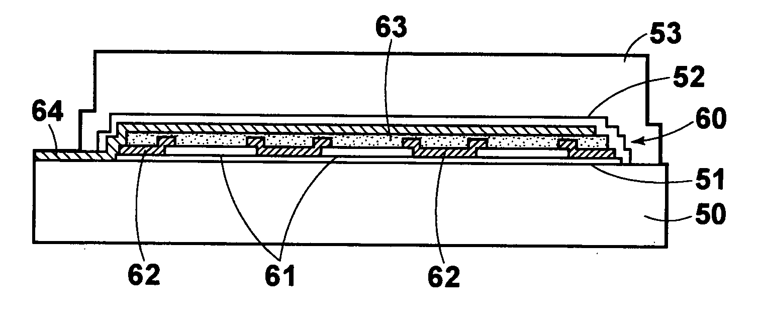
[0055]FIGS. 11A and 11B respectively show plan view and a side view of an important part of an organic EL element in accordance with an embodiment of the present invention. As shown in FIGS. 11A and 11B, the organic EL element of this embodiment comprises a lower substrate 50, a display portion 60 formed on the lower substrate 50, an upper substrate 53 as an upper layer covering the display portion 60 and the part above the display portion 60, a first gas barrier layer (sealing film) 51 disposed between the lower substrate 50 and the display portion 60 and a second gas barrier layer (passivation film) 52 disposed between the display portion 60 and the upper substrate 53.

[0056] The organic EL element of this embodiment is flexible. For this purpose, the lower and upper substrates 50 and 53 are formed of flexible and transparent resin of, for instance, macromolecular material.

[0057] The display portion 60, as in the usual organic EL element, comprises a plurality of transparent anod...


PUM


Abstract

A display device includes a substrate, a display portion formed on the substrate, an upper layer which covers the display portion, and a gas barrier layer provided between at least a part of the substrate and the display portion. The gas barrier layer is positioned near to the position which forms a neutral plane when bending moment in a direction in which the substrate is warped acts on the overall display device.

Description

BACKGROUND OF THE INVENTION [0001] 1. Field of the Invention [0002] This invention relates to a display device, and more particularly to a display device such as an organic EL (electroluminescence) element where a display portion is formed on a substrate. [0003] 2. Description of the Related Art [0004] As disclosed, for instance, in Japanese Patent No. 2911552 and Japanese Unexamined Patent Publication No. 2002-18994, there has been known an organic EL element comprising an insulating transparent substrate, a plurality of transparent anodes on the substrate spaced from each other, an organic compound layer which includes at least a light emitting layer and is formed to cover the transparent anodes, and metal cathodes opposed to the transparent anodes intervening therebetween the organic compound layer. [0005] In the organic EL element, the light emitting layer included in the organic compound layer emits light when an electric current flows between the transparent anodes and the met...

Claims


Application Information

Patent Timeline
Patent Type & Authority Applications(United States)
IPC IPC(8): H05B33/04H05B33/00G09F9/30H01L27/32H01L51/50H01L51/52H05B33/14
CPCH01L27/3281H01L2251/5338H01L51/5237H10K59/17H10K50/844H10K2102/311
Inventor OHKUBO, KAZUNOBU
Owner FUJIFILM HLDG CORP
Why Eureka
Try Eureka