Radio communication device

a radio communication and device technology, applied in the direction of antennas, antenna details, antenna earthings, etc., can solve the problems of deterioration of various antenna characteristics, difficulty in secure mounting space, and difficulty in ensuring the efficiency of the antenna device, so as to improve the antenna gain, improve the functionality, and compact size

Inactive Publication Date: 2006-02-09
LENOVO INNOVATIONS LTD HONG KONG
View PDF7 Cites 26 Cited by
  • Summary
  • Abstract
  • Description
  • Claims
  • Application Information

AI Technical Summary

Benefits of technology

[0008] A first object of the present invention to provide a radio communication device that improves antenna gain, even in a case where antenna mounting space

Problems solved by technology

However, in antenna apparatuses that are mounted inside their cases, the higher-density mounting in the radio communication device makes it difficult to secure enough mounting space.
When the mounting space is reduced, there is a basic tendency tha

Method used


Image

  • Radio communication device
  • Radio communication device
  • Radio communication device

Examples


first embodiment

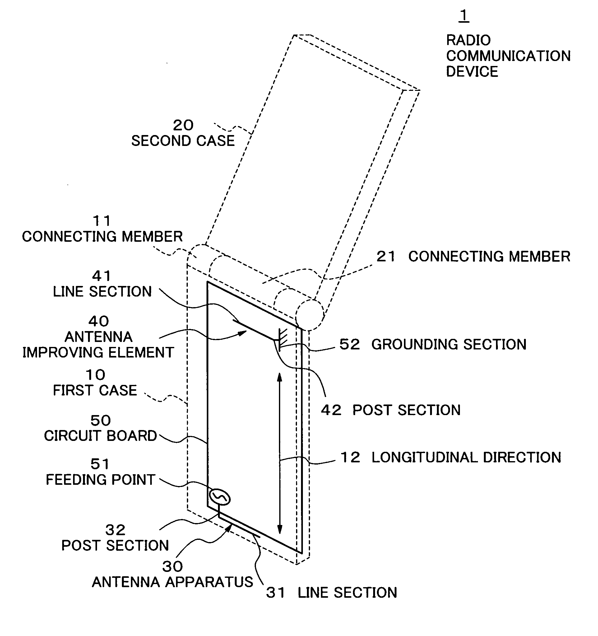
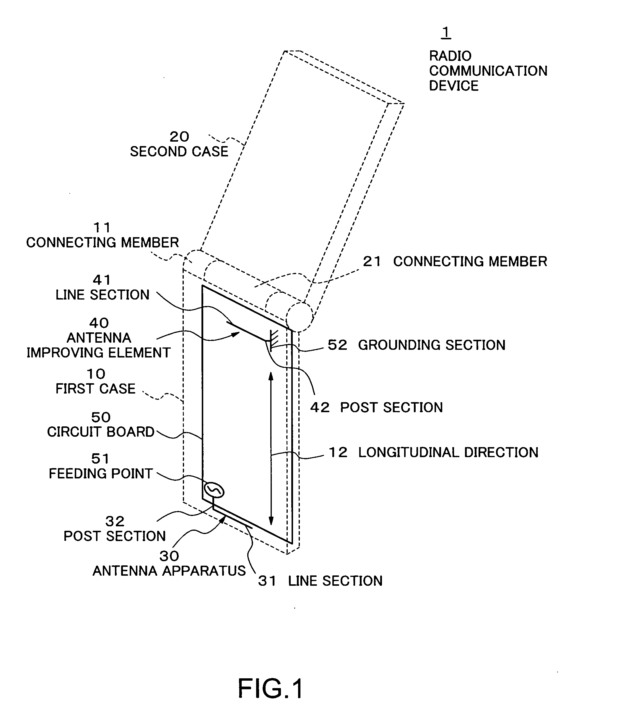
[0031] The diagrams are used to explain a first embodiment of the present invention. FIG. 1 is a perspective diagram schematically showing a construction of a radio communication device in accordance with the first embodiment of the present invention.

[0032] Referring to FIG. 1, a radio communication device 1 is a radio communication device including a cellular telephone or the like having a case that can be folded. The radio communication device 1 is provided with a first case 10, a second case 20, an antenna apparatus 30, an antenna improving element 40, and a circuit board 50.

[0033] The first case 10 is a case on which at least the antenna apparatus 30, the antenna improving element 40, and the circuit board 50 are mounted, and has a connecting member 11. The first case 10, for example, can be a case serving as an operating side having a microphone and a keyboard. The connecting member 11 is located near a central portion along a longitudinal direction 12 of the case which inclu...

second embodiment

[0046] Next, the diagrams are used to explain a second embodiment of the present invention. FIG. 6 is a perspective diagram schematically showing a construction of a radio communication device in accordance with a second embodiment of the present invention. In the second embodiment, the line section 41 of the antenna improving element 40 is formed of a metal plate. This is formed in an L-shape, including the line section 41 and the post section 42. This metal plate may be a conducting plate including carbon fiber reinforced plastic (CFRP). Other components are similar to those of the first embodiment. The line section 41 is formed using the conducting plate, thereby increasing the frequency bandwidth.

third embodiment

[0047] Next, the diagrams are used to explain a third embodiment of the present invention. FIG. 7 is a perspective diagram schematically showing a construction of a radio communication device in accordance with the third embodiment of the present invention. According to the third embodiment, the line section 41 of the antenna improving element 40 is formed to be a metal wire (or metal plate) having an L shape twisted into a meander shape. This metal wire (or metal plate) may be a conducting wire (or conducting plate) including carbon fiber reinforced plastic (CFRP). Other components are similar to those of the first embodiment. Since the line section 41 is formed in the meander shape, the line section 41 can be made compact. Furthermore, in exactly the same mounting space, the entire length of the line section 41 can be longer when using the meander shape than when formed in a straight line. Therefore, the device can handle lower frequencies.


PUM


Abstract

A radio communication device including: a case; a circuit board mounted inside the case; an antenna apparatus that is arranged inside the case and is fed electricity from the circuit board; and one or a plurality of antenna improving elements that are each arranged inside the case and each have a line section with one end grounded at one point to a ground of the circuit board and with another end open, in which the antenna improving element is arranged near a central portion of the case along a longitudinal direction thereof, and the antenna apparatus is arranged near an end of the case along the longitudinal direction thereof.

Description

BACKGROUND OF THE INVENTION [0001] 1. Field of the Invention [0002] The present invention relates to a radio communication device having a case, and more particularly to a radio communication device that allows an improved antenna gain even with a reduced antenna mounting space inside a case. [0003] 2. Description of the Related Art [0004] In recent years, due to increased functionality of cellular telephones and other radio communication devices, high-density mounting inside the cases is advancing. In particular, in a case of a radio communication device with a case that can be folded, high-density mounting has become remarkable. [0005] Japanese patent laid-open publication JP 09-326632 A (laid open on Dec. 16, 1997) discloses a technique relating to an inverted-F antenna arranged on a conducting plane, and to a passive element arranged parallel to the inverted-F antenna. [0006] Japanese patent laid-open publications JP 10-032424 A (laid open on Feb. 3, 1998), JP 11-340731 A (laid ...

Claims


Application Information

Patent Timeline
IPC IPC(8): H01Q1/24
CPCH04M1/0214H01Q1/243
Inventor HARANO, NOBUYA
Owner LENOVO INNOVATIONS LTD HONG KONG
Why Eureka
Try Eureka