Method and apparatus for correcting errors in displays

a technology for display errors and displays, applied in electrical devices, television systems, instruments, etc., can solve problems such as visual artifacts in video images displayed, image artifacts considered errors, and errors in multi-mode and pixilated video displays. achieve the effect of increasing the effective resolution and the brightness of the imag

Inactive Publication Date: 2006-02-09
WEBB JAMES R +2
View PDF13 Cites 1 Cited by
  • Summary
  • Abstract
  • Description
  • Claims
  • Application Information

AI Technical Summary

Benefits of technology

[0065] The present invention overcomes the disadvantages and limitations mentioned above by providing, in general, a system of correcting for video image errors in advance of the display device. The effective resolution and brightness of the image can be increased using merged images that overlap each area of the viewing surface with more than one position addressable illumination source. The entire viewing surface can emit light without gaps or spaces. A video signal can be over sampled to create a denser address space, corrected for display or viewing perspective distortion and enhanced to produce artifact-free video images.

Problems solved by technology

In the field of video technology, conventional methods and systems for displaying video signals on video display devices have inherent characteristics that result in visual artifacts in the displayed video images.
These artifacts are considered errors in the image, inasmuch as the picture intended for displaying and viewing differs from the image actually displayed and viewed.
Errors arise in many types of multi-mode and pixilated video displays, including computer cathode ray tube (CRT) monitors, computer liquid crystal display (LCD) monitors, DMD projectors, Micro Displays, and high definition television (HDTV) receivers.
Thus, traditional display systems and methods do not provide the best picture possible within existing standards.
One artifact common in current multi-mode and pixilated displays is less than optimal brightness and resolution.
Because of the gaps, the electronic beam in the display cannot illuminate or address the entire display surface.
Low fill factor lowers potential brightness and reduces resolution resulting in jagged edges on alphanumeric characters and diagonal lines.
This becomes annoying and even uncomfortable to the viewer, leading to eyestrain, fatigue, and loss of productivity.
However, current multi-mode and pixilated displays cannot take advantage of the over-lapping characteristics of merging and over-merging scan lines because in modes that operate at pixel densities below the merged raster density there are gaps between the pixels in the image.
These distortions are a result of the electron beam being improperly deflected across the viewing screen of the CRT.
As a result, improper deflection can occur for many reasons, including coil misadjustment and the earth's magnetic field.
Traditional methods and systems have been employed to attempt to fix these distortions by using additional deflection coils and electronic circuitry in the monitor to finely adjust the position of the electron beams; however, these methods cannot compensate completely for erroneous beam deflection, and require significant additional capital expenditures for the necessary components.
However, because of the nonlinearity of the speed of the electron gun, the video data is not displayed equally in space on the screen 300.
However, even with the cost, time, and effort in prior art techniques, nonlinearity is still not completely fixed.
Misconvergence may occur when the beams are not aimed properly at the viewing screen.
Misconvergence reduces image clarity, contrast, and resolution.

Method used


Image

  • Method and apparatus for correcting errors in displays
  • Method and apparatus for correcting errors in displays
  • Method and apparatus for correcting errors in displays

Examples


Embodiment Construction

[0083] The invention is described in detail below with reference to the drawing figures. When referring to the figures, like structures and elements shown throughout are indicated with like reference numerals.

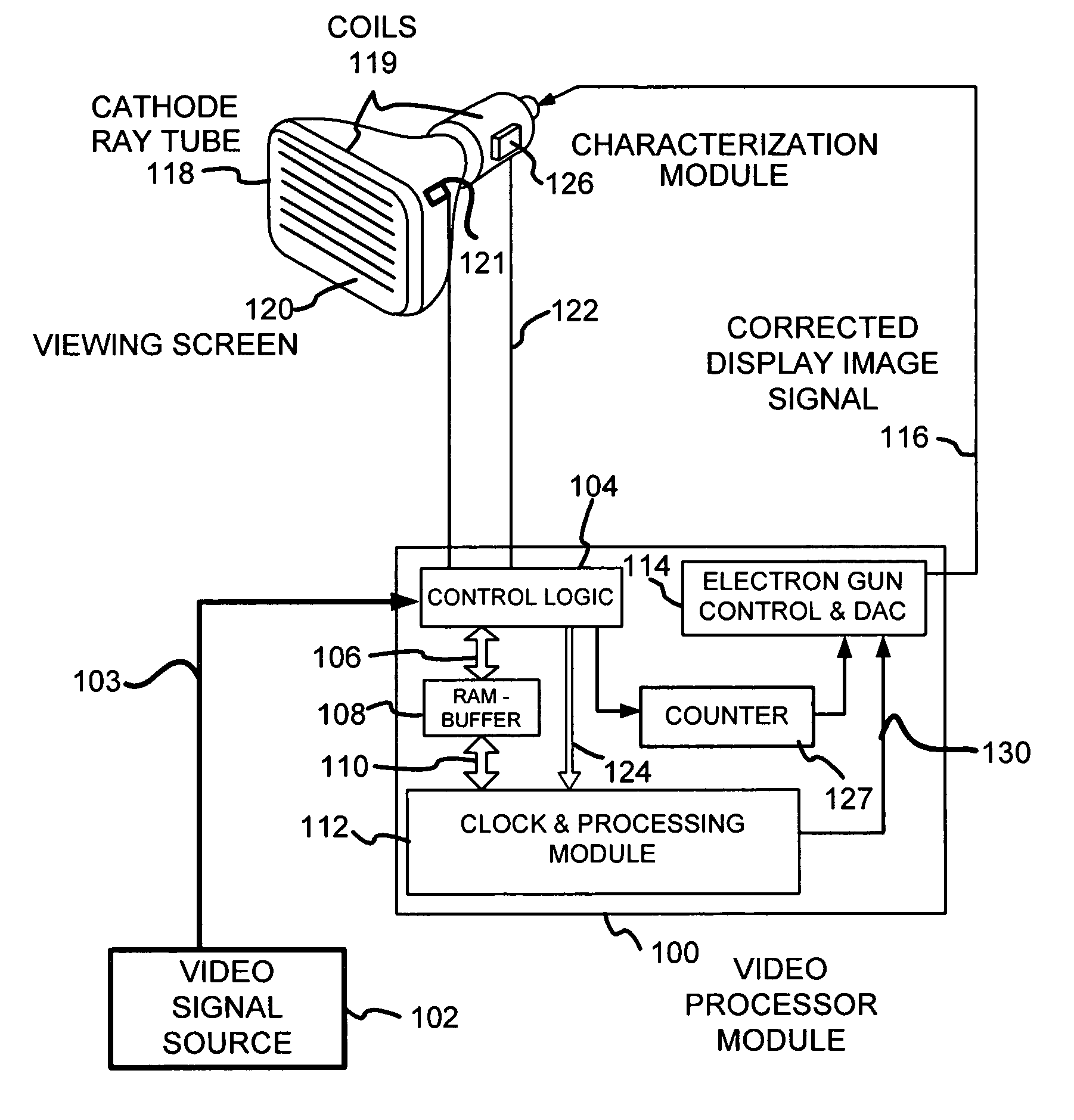
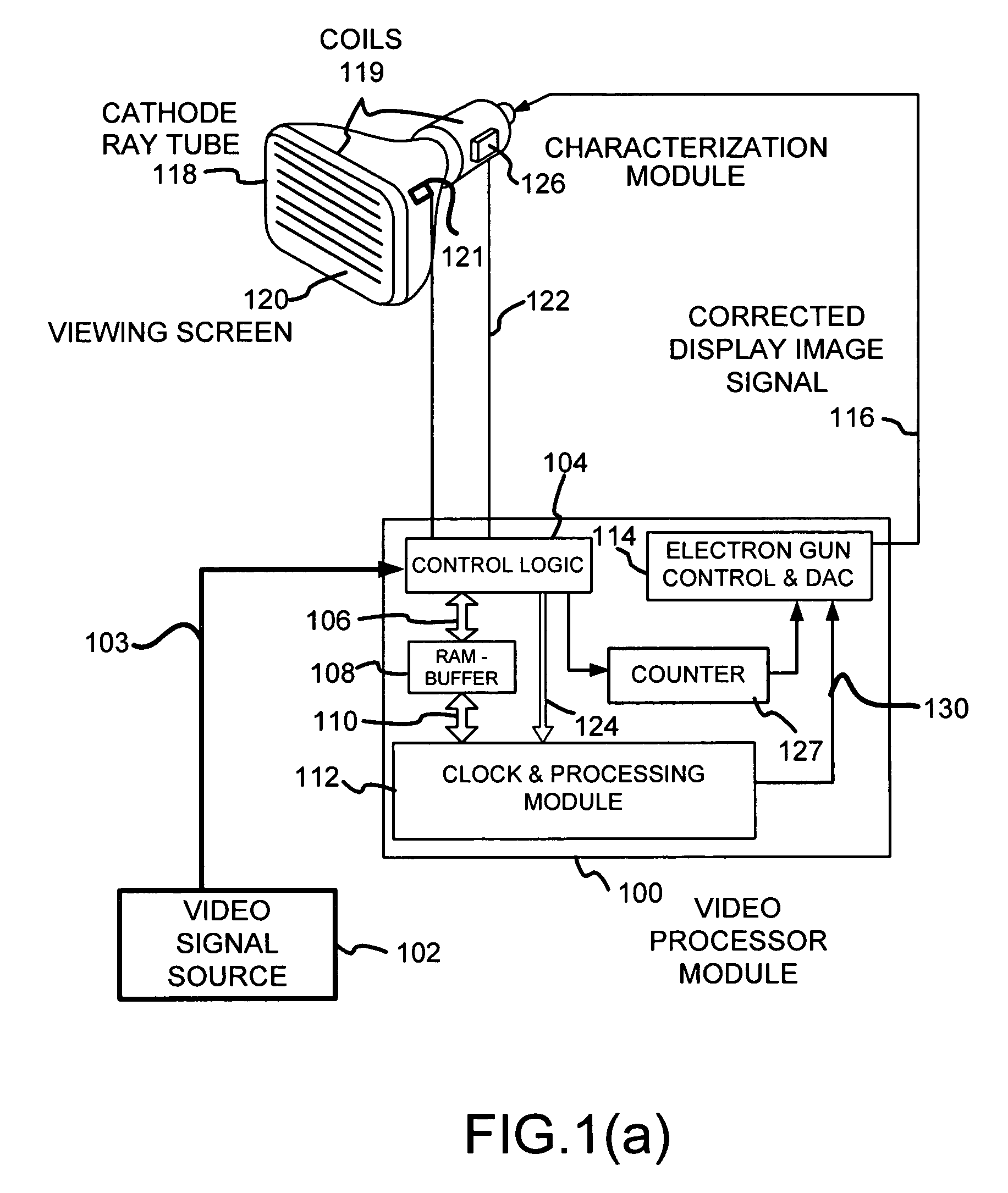
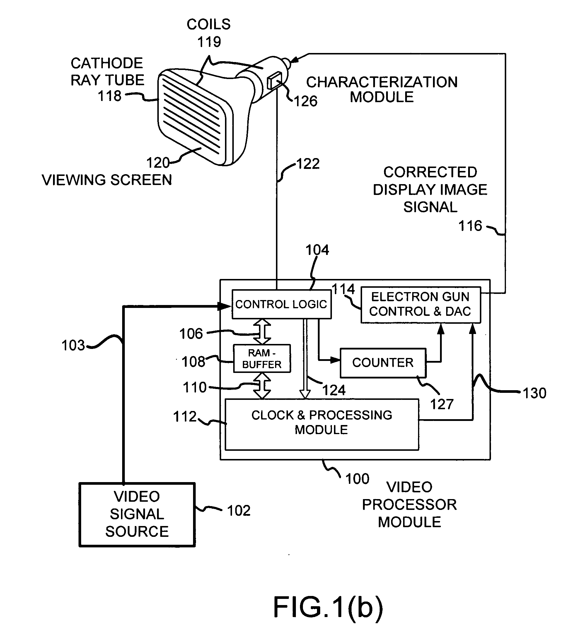
[0084]FIG. 1(a) illustrates a system for generating a corrected display image signal 116 to display an image on a screen 120 of a cathode ray tube (CRT) 118 display device. The corrected video signal adjusts the timing and content of image data to correct for errors that would otherwise be caused by the CRT 118. A video processor module 100 maps digitized video signal data to physical screen locations and generates a corrected digital image signal 130 and then an analog display image signal 602 of FIG. 6 to correct for geometric errors introduced by the CRT 118. The mapping may be viewed as occurring in time and physical space across the CRT 118. The video processor module 100 receives a video signal from a video signal source 102, in either digital or analog form. Control log...


PUM


Abstract

A system for enhancing brightness and resolution while correcting certain types of convergence, geometry, color and luminance errors caused by the display device, the viewing position or both. This system involves merging images from two or more sources, overlapping and offsetting pixels, or overlapping scanning lines ‘merged raster’ in a CRT or several (3) ‘merged rasters’ in color CRTs, and adjusting video content and timing, to compensate for the current viewing position and / or device distortion. Display and / or viewing perspective distortion characteristics are measured from the observers viewing position for the raster or each non-converged raster and stored as correction factor data in non-volatile memory. This data is used to modify the digital addressing of video image memory, to read and to correct pixel data for each image, adjust color, modify magnitude, and to drive the displays video amplifier at the correct time with the corrected amplitude and image data. Making these changes within the video path provides substantial improvements in image quality and in cost savings.

Description

RELATED APPLICATIONS [0001] This application claims priority of Patent Cooperation Treaty (PCT) application International Application Number 01 / 11293 filed Apr. 5, 2001, which claims priority of U.S. provisional application Ser. No. 60 / 194,620 filed Apr. 5, 2000; and to U.S. patent application Ser. No. 10 / 240,887, filed Oct. 4, 2002.FIELD OF THE INVENTION [0002] The present invention pertains to video displays and more particularly to enhancing brightness and resolution and correcting certain types of errors caused by display devices. DEFINITION [0003] ALIGN means to cause a video image to be adjusted so that distortion characteristics are minimized and the video image that is displayed on the cathode ray tube forms an image that is pleasing to the eye. [0004] ALIGNMENT CAMERA means the video used to generate a signal that is representative of the image displayed on the cathode ray tube in a manner described in U.S. Pat. No. 5,216,504. [0005] ALIGNMENT SPECIFICATIONS means a limit s...

Claims


Application Information

Patent Timeline
Patent Type & Authority Applications(United States)
IPC IPC(8): G09G1/14H04N17/00G09G1/00G09G1/04G09G1/06G09G1/16H04N3/233
CPCG09G1/16H04N3/2335G09G2320/02H04N3/233
Inventor WEBB, JAMES R.SELBY, STEVEBERBECEL, GHEORGHE
Owner WEBB JAMES R
Why Eureka
Try Eureka