Pen-shaped optical mouse

a mouse and pen-shaped technology, applied in the field of pen-shaped optical mouse, can solve the problems of many limitations in the design of optical systems in terms of structure and performance, the inability to maintain optimal images on the image sensor, and the variable focal length of the condenser lens or imaging unit, etc., to achieve the effect of eliminating the disadvantages involved

Inactive Publication Date: 2006-02-09
WAAWOO TECH
View PDF7 Cites 89 Cited by
  • Summary
  • Abstract
  • Description
  • Claims
  • Application Information

AI Technical Summary

Benefits of technology

[0005] Therefore, an object of the invention is to provide a pen-shaped optical mouse which eliminates disadvantages involved with conventional pen-shaped optical mice in terms of usage by employing an optical system having a new structure.

Problems solved by technology

In the case of a conventional hemispherical dome-shaped optical mouse or ball mouse, many problems caused by the structure and shape of the mouse have recently been noted in terms of usage.
However, such a depression of the condenser lens results in a variation in the focal length of the condenser lens or imaging unit.
For this reason, the image focused on the image sensor cannot be maintained in an optimal state.
In this case, however, there are many limitations in designing an optical system in terms of structure and performance.
In particular, there are limitations on the position of the image sensor and the space occupied by the optical system, so that it is impossible to arrange the function setting button of the mouse at a desired position.
In this case, however, there are various inconveniences in that the user must determine the depression of the pressure sensor in accordance with his sense of touch.
In the case of a pen-shaped structure simply using a lens, as in conventional pen-shaped mice, however, it is difficult to provide a mouse shape and size (thickness) desired by the user.

Method used


Image

  • Pen-shaped optical mouse
  • Pen-shaped optical mouse
  • Pen-shaped optical mouse

Examples


embodiment 1

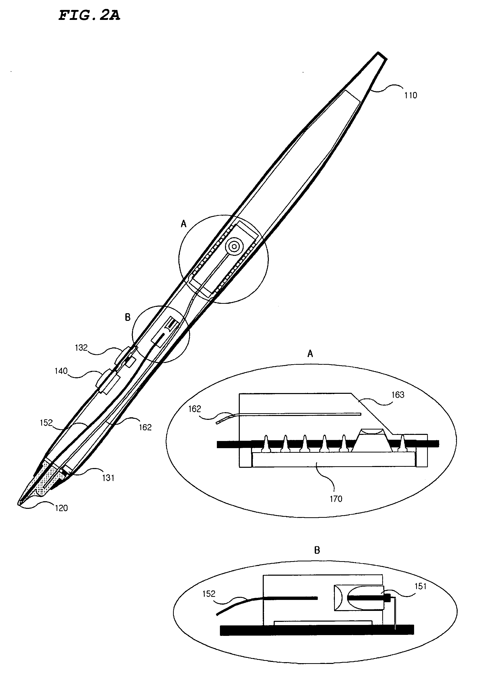
[0017]FIGS. 2A to 2F are views illustrating a pen-shaped optical mouse according to a first embodiment of the present invention, respectively.

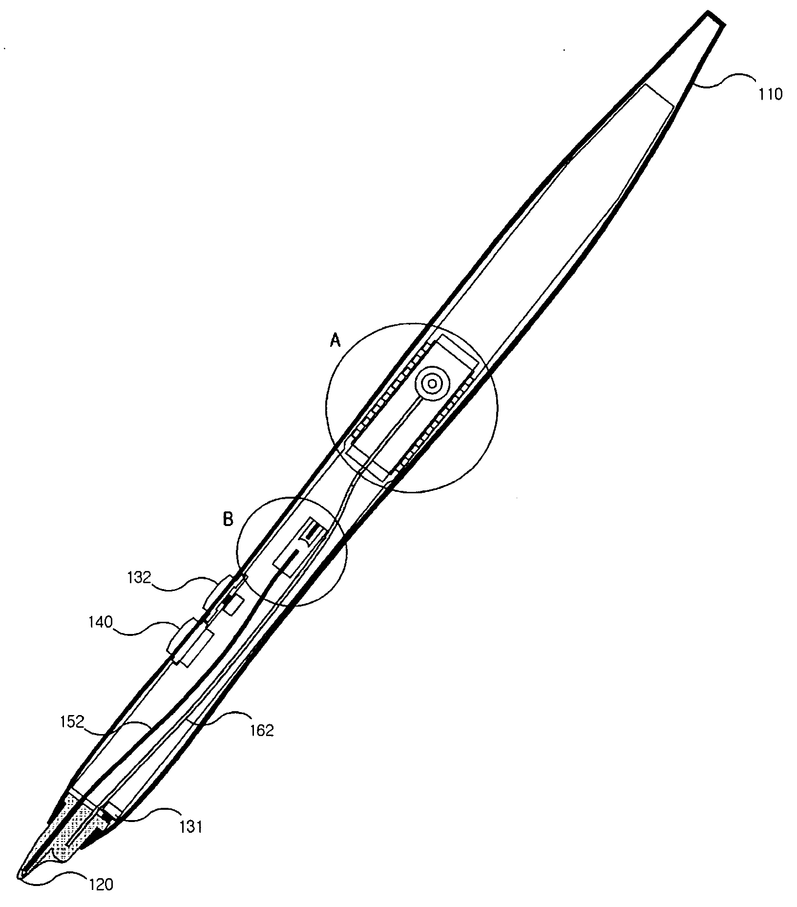
[0018] Referring to FIG. 2A to 2C, the pen-shaped optical mouse according to the first embodiment of the present invention includes a mouse body 110, along with an optical tip member 120, first and second click buttons 131 and 132, a wheel button sensor 140 or contact button sensor, an illuminating unit 150, a condenser lens 161, a bundled optical fiber 162, an imaging unit 163, an image sensor 170, and a microcomputer (not shown), all of which are installed in the mouse body 110.

[0019] The mouse body 110 has the shape of a pen which is a writing instrument most familiar to the public. Since the mouse of the present invention has such a pen shape, the user does not feel fatigued even after using the mouse. Also, the mouse can be conveniently carried by the user, and easily used even in a narrow space, while having excellent functions in asso...

embodiment 2

[0038]FIG. 3 is a schematic view illustrating a pen-shaped optical mouse according to a second embodiment of the present invention.

[0039] The pen-shaped optical mouse according to the second embodiment of the present invention includes a mouse body, along with an optical tip member, click buttons, a wheel button sensor or contact button sensor, an illuminating unit, a condenser lens, a bundled optical fiber, an imaging unit, an image sensor, and a microcomputer, all of which are installed in the mouse body. This pen-shaped optical mouse has the same configuration as that of the first embodiment, except for the mounted positions of the illuminating unit and condenser lens. Accordingly, no further description will be given with respect to the identically configured elements.

[0040] Referring to FIG. 3 along with FIG. 2A, the illuminating unit 150 of the pen-shaped optical mouse according to this embodiment is arranged such that light illuminated therefrom is directly irradiated onto ...

embodiment 3

[0043]FIG. 4 is a schematic view illustrating a pen-shaped optical mouse according to a third embodiment of the present invention.

[0044] The pen-shaped optical mouse according to the third embodiment of the present invention includes a mouse body, along with a ball, click buttons, a wheel button sensor or contact button sensor, an illuminating unit, a condenser lens, a bundled optical fiber, an imaging unit, an image sensor, and a microcomputer, all of which are installed in the mouse body. This pen-shaped optical mouse has the same configuration as that of the first embodiment, except that it includes the ball, in place of the optical tip member, so that the position of the region where light from the illuminating unit is irradiated, and the mounted position of the condenser lens are different from those of the first embodiment. Accordingly, no further description will be given with respect to the same configuration.

[0045] Referring to FIG. 4 along with FIG. 2A, the ball 210 has ...


PUM

PropertyMeasurementUnit
incidence angleaaaaaaaaaa
angleaaaaaaaaaa

Abstract

Disclosed is a pen-shaped optical mouse. The optical mouse has an optical fiber on the optical path of illuminating light, and an optical fiber bundle on the optical path of reflected light, respectively. The optical system of the optical mouse is realized irrespective of the optical paths and their lengths, showing a good image-transmitting feature to transmit good image to an image sensor. An image is input to the image sensor through an end of an optical tip where the image directly contacts a reflecting surface, which enhances the accuracy of the pen-shaped optical mouse since there is no change in the location of a mouse pointer or a focal length in spite of the change in the angle between the pen-shaped optical mouse and the reflecting surface.

Description

TECHNICAL FIELD [0001] The present invention relates to a pen-shaped optical mouse, and more particularly to a pen-shaped optical mouse which employs an optical system operating irrespective of any optical transmission path and distance, so that it operates irrespective of its angle defined with respect to a reflection surface. BACKGROUND ART [0002] In a computer, a mouse is widely used as an input device, along with a keyboard. In the case of a conventional hemispherical dome-shaped optical mouse or ball mouse, many problems caused by the structure and shape of the mouse have recently been noted in terms of usage. In order to solve such problems, efforts to provide a mouse having a pen-shaped structure familiar to the public have been made. [0003]FIG. 1 is a schematic view explaining the operating concept of a conventional pen-shaped optical mouse. [0004] Referring to FIG. 1, light emitted from a light emitting unit included in the pen-shaped optical mouse is reflected from a refle...

Claims


Application Information

Patent Timeline
Patent Type & Authority Applications(United States)
IPC IPC(8): G09G5/00G06F3/03G06F3/033
CPCG06F3/0312G06F3/0317G06F3/03545G06F3/03546
Inventor KANG, BYUNG-GEUN
Owner WAAWOO TECH
Why Eureka
Try Eureka