Automotive electrical system

a technology for electrical systems and vehicles, applied in the direction of dc network load balancing, electric devices, transportation and packaging, etc., can solve the problems of unable to use large vehicles, such as light trucks, with conventional vehicle electric systems, and limited alternator current output capability,

Inactive Publication Date: 2006-02-09
TEMIC AUTOMOTIVE OF NORTH AMERICA
View PDF20 Cites 59 Cited by
  • Summary
  • Abstract
  • Description
  • Claims
  • Application Information

AI Technical Summary

Problems solved by technology

However, the automotive industry has been reluctant to transition to 42 volt electrical systems because of increased costs.
As an example, high current loads, such as electric power steering (EPS), cannot practically be used in larger vehicles, such as light trucks, with conventional vehicle electric systems.
However, at low vehicle speeds, e.g. in a parking lot, the engine is typically at or near idle and thus alternator current output capability is severely limited.
As a result, the vehicle electrical system cannot supply the power needed by EPS without the 12 volt bus experiencing a temporary voltage dip.
When this voltage dip occurs, a variety of objectionable performance is experienced from various electrical systems, for example dimming of the vehicle lights.
Additionally, it is also likely that the required EPS current cannot be supplied, and thus the desired steering response will not occur.
The amount of energy drawn from the supercapacitor is not optimized because the supercapacitor is connected directly across the load, thereby limiting the voltage drop across the supercapacitor.
This system is disadvantageous in that the energy supplied to the load is limited solely to that in the supercapacitor.

Method used


Image

  • Automotive electrical system
  • Automotive electrical system
  • Automotive electrical system

Examples


Embodiment Construction

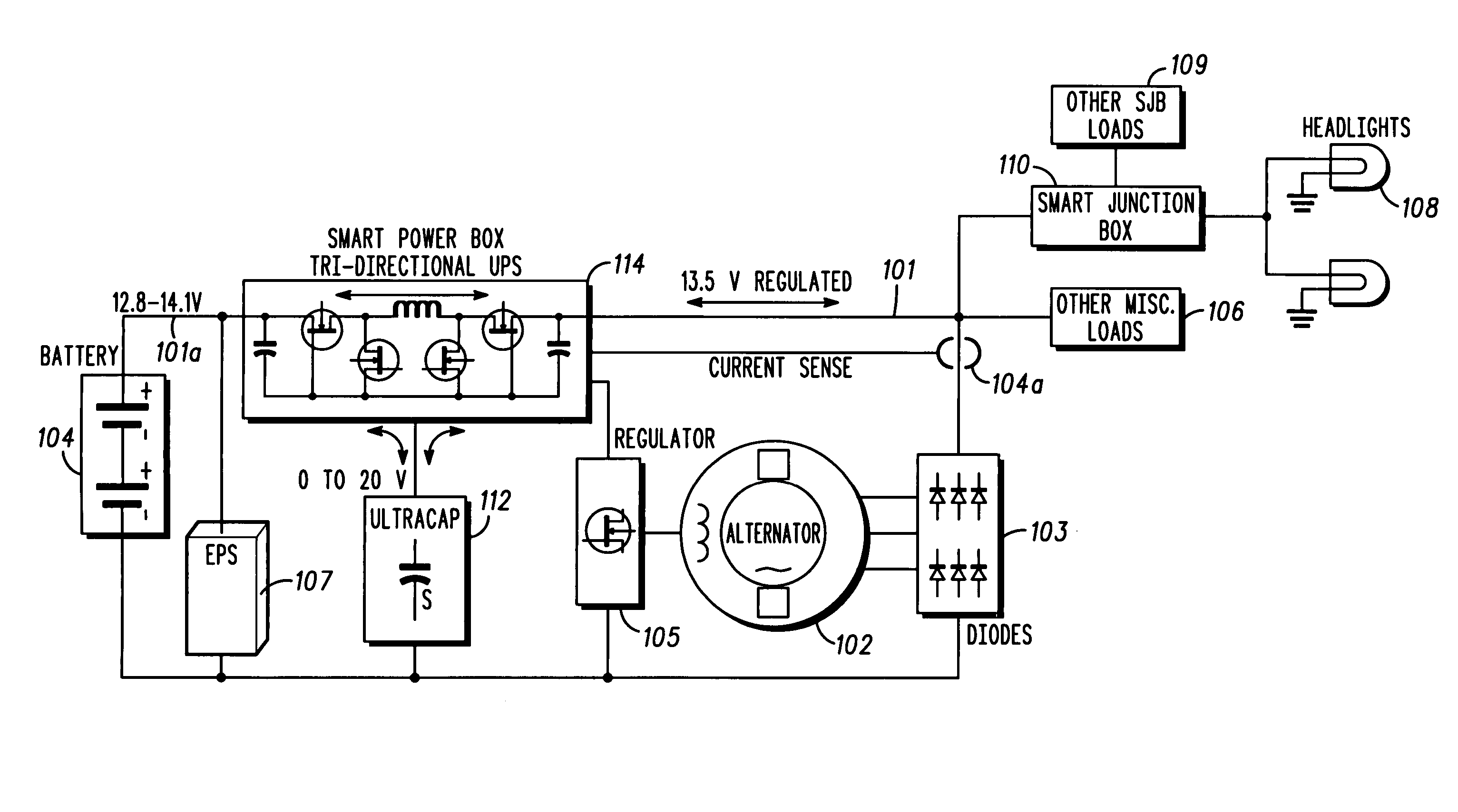
[0018] What is described are electrical system topologies intended to mitigate the impact of large intermittent loads on a 12 volt vehicle power distribution system. In some embodiments, the intermittent load is disconnected from the remainder of the system and the voltage supplied to this load is allowed to fluctuate. In other embodiments, the voltage to critical loads (e.g., the headlights) is regulated independently of the voltage supplied to the remainder of the system. The different topologies described can be grouped into categories, each corresponding to a different solution technique.

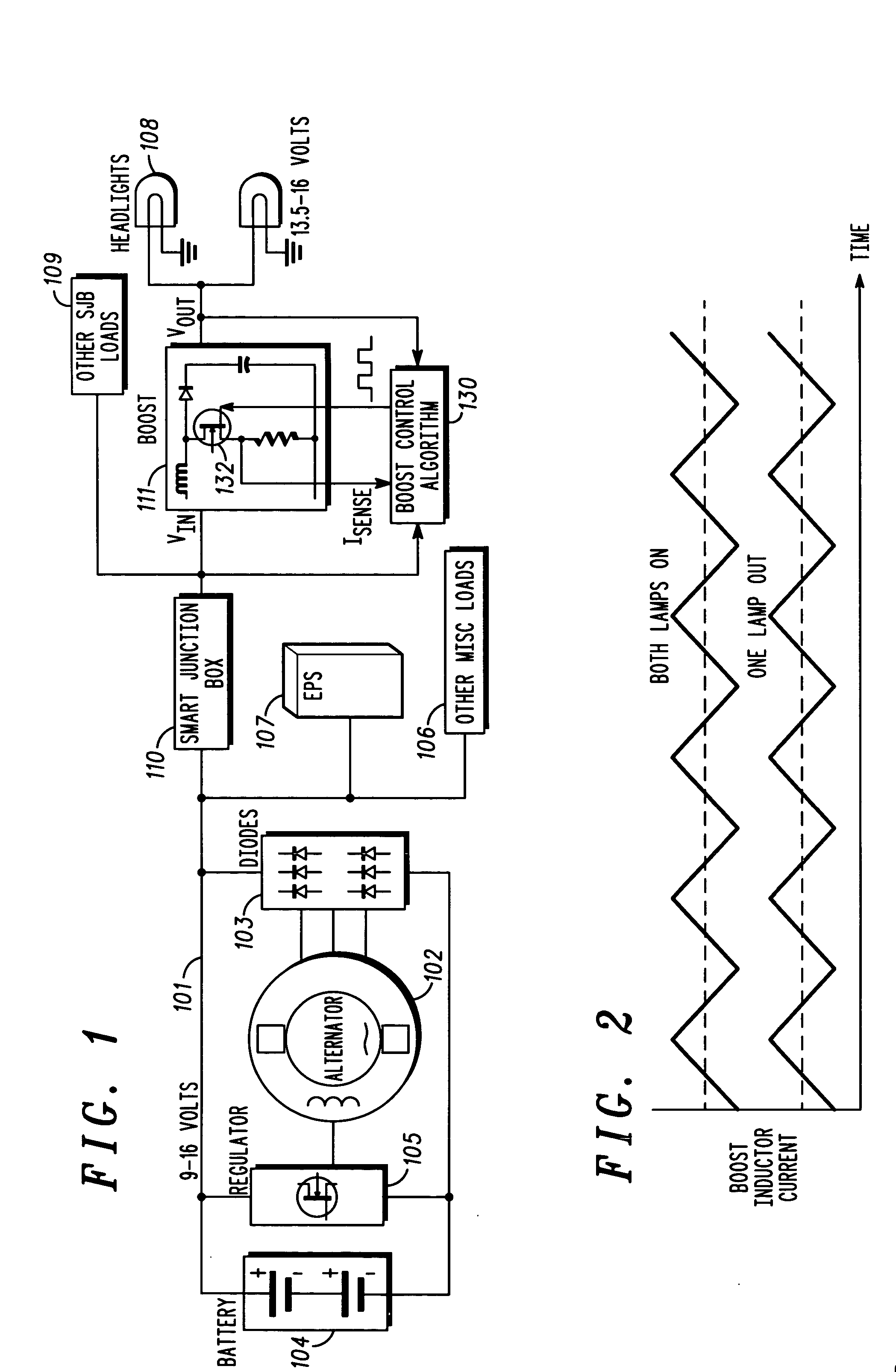
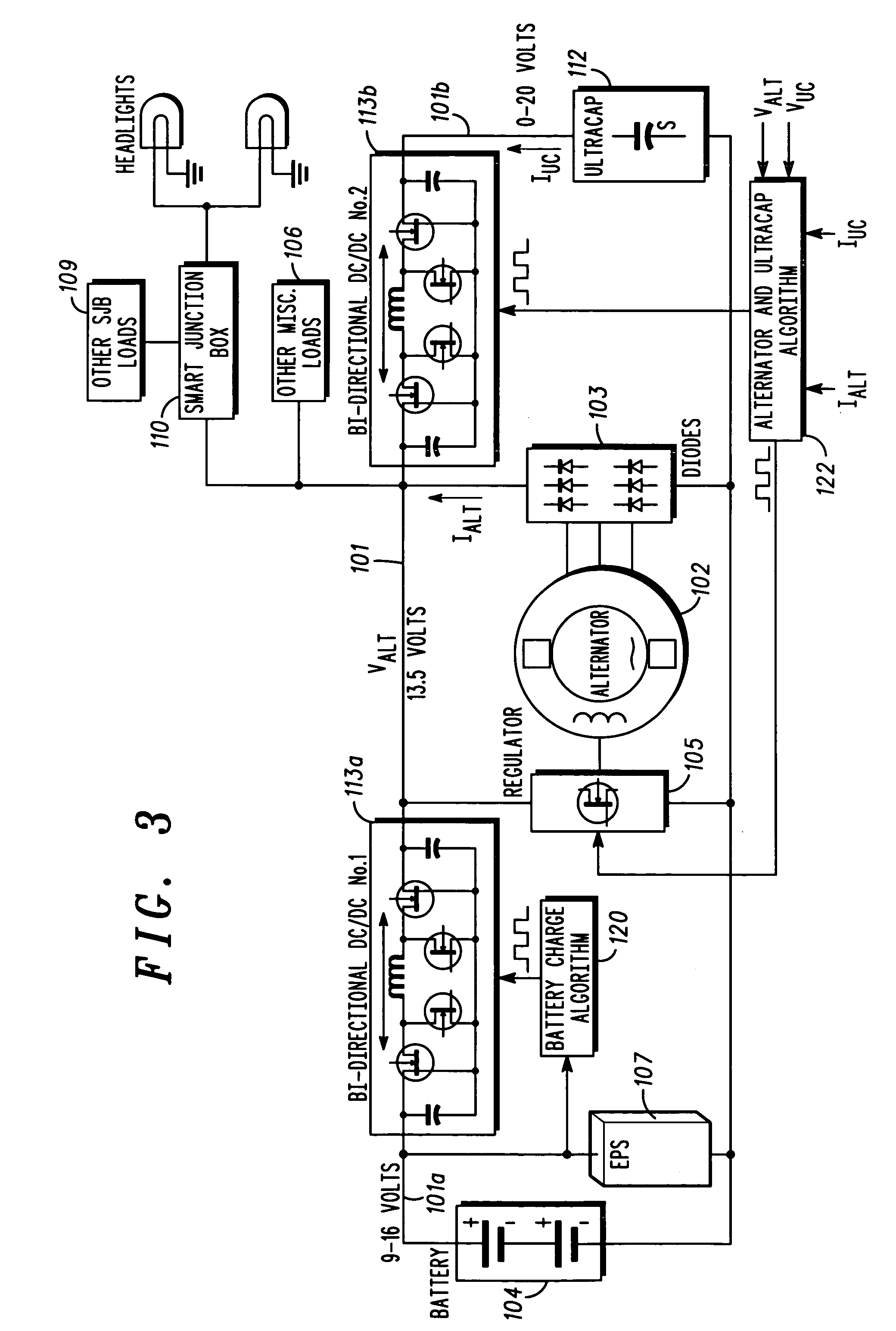
[0019] One approach is to regulate the voltage to the critical loads. A solution in this mode is to provide a separate boost converter for critical loads, as illustrated in FIG. 1. A second approach is to isolate the intermittent load (e.g., EPS) that causes the drop in system voltage. These solutions typically involve multi-directional DC / DC converters and are illustrated in FIGS. 3-7. The thi...


PUM


Abstract

Disclosed herein are a variety of different electrical system topologies intended to mitigate the impact of large intermittent loads on a 12 volt vehicle power distribution system. In some embodiments the intermittent load is disconnected from the remainder of the system and the voltage supplied to this load is allowed to fluctuate. In other embodiments, the voltage to critical loads is regulated independently of the voltage supplied to the remainder of the system. The different topologies described can be grouped into three categories, each corresponding to a different solution technique. One approach is to regulate the voltage to the critical loads. A second approach is to isolate the intermittent load that causes the drop in system voltage. The third approach is to use a different type of alternator that has a faster response than the conventional Lundell wound field machine.

Description

[0001] The present application claims priority from provisional application Ser. No. 60 / 599,328, entitled “Automotive Electrical System Configuration,” filed Aug. 6, 2004, which is commonly owned and incorporated herein by reference in its entirety. [0002] The present application is related to non-provisional application, Ser. No. ______, entitled “Automotive Electrical System Configuration Using a Two Bus Structure,” attorney docket IS01801AIC, filed Aug. 24, 2004, which is commonly owned and incorporated herein by reference in its entirety.FIELD OF THE INVENTION [0003] This invention in general relates to automotive electrical systems and, more particularly, to configurations of automotive electrical power systems adapted for use with high power loads. BACKGROUND OF THE INVENTION [0004] The 12 volt systems used in today's automobiles are required to supply ever increasing currents as the load on the system continues to increase. This increase is due to a combination of increasing ...

Claims


Application Information

Patent Timeline
Patent Type & Authority Applications(United States)
IPC IPC(8): H02H3/00
CPCB60R16/023H02J1/14Y02T10/7022Y02T10/7005H02J7/1438H02J2310/46Y02T10/70
Inventor O'GORMAN, PATRICK A.REMBOSKI, DONALD J.STEPHENS, DENNIS L.
Owner TEMIC AUTOMOTIVE OF NORTH AMERICA
Why Eureka
Try Eureka